Electrical Engineering (EE) Exam  >  Electrical Engineering (EE) Tests  >  GATE Electrical Engineering (EE) Mock Test Series 2025  >  Test: First Order RL & RC Circuits- 2 - Electrical Engineering (EE) MCQ

Test: First Order RL & RC Circuits- 2 - Electrical Engineering (EE) MCQ


Test Description

15 Questions MCQ Test GATE Electrical Engineering (EE) Mock Test Series 2025 - Test: First Order RL & RC Circuits- 2

Test: First Order RL & RC Circuits- 2 for Electrical Engineering (EE) 2024 is part of GATE Electrical Engineering (EE) Mock Test Series 2025 preparation. The Test: First Order RL & RC Circuits- 2 questions and answers have been prepared according to the Electrical Engineering (EE) exam syllabus.The Test: First Order RL & RC Circuits- 2 MCQs are made for Electrical Engineering (EE) 2024 Exam. Find important definitions, questions, notes, meanings, examples, exercises, MCQs and online tests for Test: First Order RL & RC Circuits- 2 below.
Solutions of Test: First Order RL & RC Circuits- 2 questions in English are available as part of our GATE Electrical Engineering (EE) Mock Test Series 2025 for Electrical Engineering (EE) & Test: First Order RL & RC Circuits- 2 solutions in Hindi for GATE Electrical Engineering (EE) Mock Test Series 2025 course. Download more important topics, notes, lectures and mock test series for Electrical Engineering (EE) Exam by signing up for free. Attempt Test: First Order RL & RC Circuits- 2 | 15 questions in 45 minutes | Mock test for Electrical Engineering (EE) preparation | Free important questions MCQ to study GATE Electrical Engineering (EE) Mock Test Series 2025 for Electrical Engineering (EE) Exam | Download free PDF with solutions
Test: First Order RL & RC Circuits- 2 - Question 1

Laplace transform analysis gives

Test: First Order RL & RC Circuits- 2 - Question 2

The Laplace transform of the derivative of the signal f(t) = e-t u(t) is

Detailed Solution for Test: First Order RL & RC Circuits- 2 - Question 2

The derivative of function f(t) is
f'(t) = e-tδ (t) + u (t) (-e-t)
= -e-t u(t) + e-tδ(t)

1 Crore+ students have signed up on EduRev. Have you? Download the App
Test: First Order RL & RC Circuits- 2 - Question 3

For a series R - C circuit excited by a dc voltage of 20 V, and with time-constant τ seconds, the voltage across the capacitor at time t = τ is given by

Detailed Solution for Test: First Order RL & RC Circuits- 2 - Question 3

Vc(t) = V(1 - e-t/τ) volts
V = 20 volt (given)
At t = τ, Vc|t = τ = 20 (1 - e-1) volts

Test: First Order RL & RC Circuits- 2 - Question 4

The Laplace-transform equivalent of a given network will have 7/5 F capacitor replaced by 5

Detailed Solution for Test: First Order RL & RC Circuits- 2 - Question 4

Test: First Order RL & RC Circuits- 2 - Question 5

An RC circuit has a capacitor C = 2 μF in series with a resistance R = 1 MΩ The time of 6 secs will be equal to

Detailed Solution for Test: First Order RL & RC Circuits- 2 - Question 5

Time constant of series RC circuit is
τ = RC = 1 x 106 x 2 x 10-6
= 2 secs
Hence, time of 6 seconds will be equal to 3τ = 3 times of time constant.

Test: First Order RL & RC Circuits- 2 - Question 6

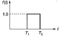
The Laplace transform of the gate function shown below is
Detailed Solution for Test: First Order RL & RC Circuits- 2 - Question 6

From the given waveform, we have

∴ 

Test: First Order RL & RC Circuits- 2 - Question 7

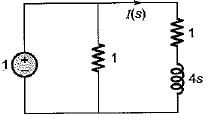
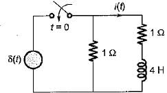
Assuming initial condition to be zero, the current i(t) in the circuit shown below is
Detailed Solution for Test: First Order RL & RC Circuits- 2 - Question 7

The given circuit in Laplace domain is shown below.

Here 

(Using current divider theorem)

or, i(t) = 0.25 e-0-5t u(t)

Test: First Order RL & RC Circuits- 2 - Question 8

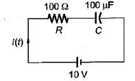
A 10 volts step voltage is applied across a RC series circuit at t = 0 having R = 100 Ω, and C = 100 μF.
The values of i(t) and di(t)/dt at t = 0 are respectively given by

Detailed Solution for Test: First Order RL & RC Circuits- 2 - Question 8


At t = 0, capacitor acts as short-circuit.
So, 

Time constant of given circuit is
τ = RC = 100 x 100 x 10-6
= 10-2 sec = 0.01 sec
With zero initial condition, current in the series RC circuit is


Hence, 
di/dt = -10 e-100t
i(0+) = 0.1 A

Test: First Order RL & RC Circuits- 2 - Question 9

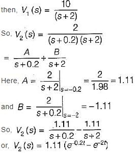
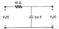
If the input voltage V1(t) = 10 e-2t V then, the output voltage V2(t) for the circuit shown below is
Detailed Solution for Test: First Order RL & RC Circuits- 2 - Question 9

Given circuit is a low-pass filter having transfer function


When, V1(t) = 10e-2t

Test: First Order RL & RC Circuits- 2 - Question 10

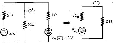
In the circuit shown below, the switch 'S' is opened at t = 0. Prior to that, switch was closed.
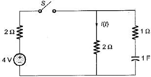
The current i(t) is at t = 0+ is

Detailed Solution for Test: First Order RL & RC Circuits- 2 - Question 10

For t = 0-, switch Sis closed. Hence, in steady state capacitor will act as open circuit.
Thus, V0(0-) = VC(0+) = 2 volts
The circuit at t = 0+ is shown below where,
cananitor ants as a constant voltage source.

Using source transformation,

and 

Hence, 

Test: First Order RL & RC Circuits- 2 - Question 11

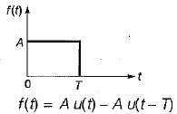
A rectangular pulse of duration T and magnitude A has the Laplace transform

Detailed Solution for Test: First Order RL & RC Circuits- 2 - Question 11


∴ 

Test: First Order RL & RC Circuits- 2 - Question 12

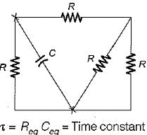
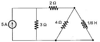
The time constant of the circuit shown below is
Detailed Solution for Test: First Order RL & RC Circuits- 2 - Question 12

Reg across inductor 

(5 A C.S open circuited)
∴ Time constant of RL circuit is

Test: First Order RL & RC Circuits- 2 - Question 13

Assertion (A): Laplace transform is preferred for solving networks involving higher order differential equations.
Reason (R): The classical method for solving differential equations of higher order is quite cumbersome.

Test: First Order RL & RC Circuits- 2 - Question 14

Assertion (A): In a purely capacitive circuit, the current wave is more distorted than the voltage wave.
Reason (R): The harmonics in the current wave are increased in proportion to their frequency numbers.

Test: First Order RL & RC Circuits- 2 - Question 15

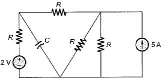
The time constant of the circuit shown below is
Detailed Solution for Test: First Order RL & RC Circuits- 2 - Question 15

For finding time constant of the circuit 5 A current source is open circuited and 2 V voltage source is short circuited.


Ceq = C
∴ 

25 docs|247 tests
Information about Test: First Order RL & RC Circuits- 2 Page
In this test you can find the Exam questions for Test: First Order RL & RC Circuits- 2 solved & explained in the simplest way possible. Besides giving Questions and answers for Test: First Order RL & RC Circuits- 2, EduRev gives you an ample number of Online tests for practice

Top Courses for Electrical Engineering (EE)

Download as PDF

Top Courses for Electrical Engineering (EE)