Electrical Engineering (EE) Exam  >  Electrical Engineering (EE) Tests  >  Electromagnetic Fields Theory (EMFT)  >  Test: Magnetomotive Force - Electrical Engineering (EE) MCQ

Test: Magnetomotive Force - Electrical Engineering (EE) MCQ


Test Description

10 Questions MCQ Test Electromagnetic Fields Theory (EMFT) - Test: Magnetomotive Force

Test: Magnetomotive Force for Electrical Engineering (EE) 2024 is part of Electromagnetic Fields Theory (EMFT) preparation. The Test: Magnetomotive Force questions and answers have been prepared according to the Electrical Engineering (EE) exam syllabus.The Test: Magnetomotive Force MCQs are made for Electrical Engineering (EE) 2024 Exam. Find important definitions, questions, notes, meanings, examples, exercises, MCQs and online tests for Test: Magnetomotive Force below.
Solutions of Test: Magnetomotive Force questions in English are available as part of our Electromagnetic Fields Theory (EMFT) for Electrical Engineering (EE) & Test: Magnetomotive Force solutions in Hindi for Electromagnetic Fields Theory (EMFT) course. Download more important topics, notes, lectures and mock test series for Electrical Engineering (EE) Exam by signing up for free. Attempt Test: Magnetomotive Force | 10 questions in 30 minutes | Mock test for Electrical Engineering (EE) preparation | Free important questions MCQ to study Electromagnetic Fields Theory (EMFT) for Electrical Engineering (EE) Exam | Download free PDF with solutions
Test: Magnetomotive Force - Question 1

100 maxwells = _______ magnetic line(s).

Detailed Solution for Test: Magnetomotive Force - Question 1

Concept:

Maxwell Unit:

A maxwell is a non-SI unit.

One maxwell is the total flux across a surface of one square centimetre perpendicular to a magnetic field of strength one gauss.

1 Line is equivalent to 1 maxwell 

100 maxwells =  100 magnetic line

Additional Information 

1 maxwell = 1 gauss × cm2 .... (1)

Since gauss is a CGS unit and it is given by,

1 gauss = 10-4 Tesla And, 1 cm = 10-2 m

From equation (1),

1 maxwell = 10-4 Tesla × 10-4 m2 or,

1 maxwell = 10-4 wb/m2 × 10-4 m2 (T = wb/m2)

Test: Magnetomotive Force - Question 2

A magnetising force of 800 AT/m will produce a flux density of ______ in air.

Detailed Solution for Test: Magnetomotive Force - Question 2

Concept:

Magnetic field strength or field intensity (H) is the amount of magnetizing force.

Magnetic flux density (B) is the amount of magnetic force induced on the given body due to the magnetizing force H.

The relation between B and H is,

B = μH

Where, 

μ = μ0 μr =  Permeability of the material

μ0 = Absolute permeability = 4π x 10-7 H/m

μr = relative permeability 

Calculation:

Given-

H = 800 AT/m , μr = 1 (∵ for air)

So that flux density for given magnetising force will be

B = 4π x 10-7 x 800 = 1.0053 x 10⁻³

B ≈ 1 mWb/m2

1 Crore+ students have signed up on EduRev. Have you? Download the App
Test: Magnetomotive Force - Question 3

In order to produce a flux of 100 μwb in an air gap of length 0.2 mm and area of cross-section is 1 cm2, the MMF required is:

Detailed Solution for Test: Magnetomotive Force - Question 3

Magnetomotive force (MMF):

The current flowing in an electric circuit is due to the existence of electromotive force similarly magnetomotive force (MMF) is required to drive the magnetic flux in the magnetic circuit. The magnetic pressure, which sets up the magnetic flux in a magnetic circuit is called Magnetomotive Force.

The strength of MMF is equal to the product of the current and no. of turns of the coil

MMF can be expressed as

MMF = N I = (Flux) x (Reluctance)

The SI unit of MMF is ampere-turn (AT).

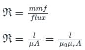
The Reluctance (S) is given as,

Calculation:

The Airgap length (l) = 0.2 mm = 0.2 × 10m

Cross-section area (A) = 1 cm2 = 10-4 m2

Reluctance of airgap will be

MMF = Flux × reluctance

Test: Magnetomotive Force - Question 4

A rectangular iron core has three coils as shown in the given figure. The number of turns of the coils are Na = 300, Nb = 600 and Nc = 600, and the respective currents are 1.5 A, 4 A and 3 A. Find the total magnetomotive force.
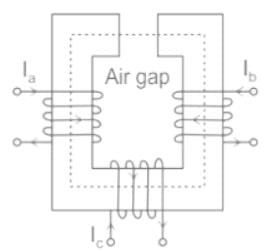
Detailed Solution for Test: Magnetomotive Force - Question 4

Concept:

The magneto motive force ( MMF ) for a coil having N turns, carrying current I is given by

MMF = N × I  and is responsible for causing the Flux.

The direction of Flux is given by Flemings Right hand curl rule.

Application:

Given:

Na = 300, Ia = 1.5 A, Nb = 600, Ib = 4 A, Nc = 600, Ic = 3 A

Let us assume direction of flux in upward direction be +ve and downward direction be -ve

For Coil A, MMFa = Na Ia = 300 × 1.5 = 450 AT ( + )

For coil B, MMFb = Nb I= 600 × 4 = 2400 AT ( + )

For coil C, MMFc = Nc Ic = 600 × 3 = 1800 AT ( - )

Net MMF = 450 + 2400 - 1800 = 1050 AT

Note: The direction of flux for coil a and coil b are in same direction and in opposite direction for coil c.

Test: Magnetomotive Force - Question 5

Magnetic field strength is quantified in terms of:

Detailed Solution for Test: Magnetomotive Force - Question 5

Magnetic pole strength:

  • It is a measure of the force exerted by one face of a magnet on a face of another magnet when both magnets are represented by equal and opposite poles.
  • Symbol: m.

Units:

  • There are two possible units for magnetic pole strength in SI units, depending on how the pole force is described.
  • If you describe this as force per unit field B, then the SI unit is the ampere-meter (Am).
  •  It can also be defined as the force per field of unit H, in this case, the unit SI is the weber (Wb).
  • Unit of magnetic pole strength is Am or Wb.

Magnetic field intensity (H):

  • Magnetic field strength refers to the ratio of the MMF which is required to create a certain Flux Density (B) within a certain material per unit length of that material. Some experts also call is as the magnetic field intensity.
  • Furthermore, the magnetic flux refers to the total number of magnetic field lines that penetrate an area. Furthermore, the magnetic flux density tends to diminish with increasing distance from a straight current-carrying wire or a straight line which connects a pair of magnetic poles around which the magnetic field is stable.
  • Magnetic field strength refers to a physical quantity that is used as one of the basic measures of the intensity of the magnetic field. The unit of magnetic field strength happens to be ampere per meter or A/m.

B = μ H

B in terms of force is expressed according to Lorentz force equation as

Where F is force in newtons (N)

             q is charge

             v is velocity.

Therefore H = N / Am

                   H = N / Wb. 

Test: Magnetomotive Force - Question 6

Considering electromagnetic circuits, which of the following is unit less?

Detailed Solution for Test: Magnetomotive Force - Question 6

Permeability:

  • In Electromagnetism, permeability is the measure of magnetization that a material obtains in response to an applied magnetic field.
  • It is denoted by the greek letter μ, it is measured in Henries per meter (H/ m).
  • Relative permeability is the ratio of the permeability of a specific medium to the permeability of free space.
  • Since relative permeability is the ratio of two quantities with the same units, so it is unit less.

Where μ = permeability of a specific medium

μ = Permeability of free space

μr = Relative permeability 

Conclusion: Hence, it is a dimensionless quantity and is equal to 1 for a vacuum (Free Space).

Additional Information

Permeance:

  • It is the measure of the ease with which flux can be set up in a material.
  • It is analogous to the conductance of the electrical circuit.
  • In Electromagnetism, permeance is the inverse of reluctance.

Reluctance:

  • The reluctance of a magnetic material is its ability to oppose the flow of magnetic flux.
  • It is analogous to the resistance of the electrical circuit.
  • It is the ratio of the magnetomotive force (m.m.f) to the magnetic flux in the magnetic circuit.

Absolute Permeability:

  • Absolute permeability is given by the ratio of magnetic flux density (B) to the intensity of the magnetic field in the particular medium.
  • The absolute permeability of the free space is equal to a constant equal to 4π × 10-7 H/ m.
  • The absolute permeability of the other medium is given by the formula:
  • μ = μ∘μr.
Test: Magnetomotive Force - Question 7

If an electron, a neutron and a proton having same momenta enter perpendicularly to a magnetic field, then: 

Detailed Solution for Test: Magnetomotive Force - Question 7
  • The magnetic force exerted on a charged particle moving in a magnetic field is given by the Lorentz force equation, which depends on the charge of the particle. Since the neutron is uncharged, it will not experience a magnetic force and will move undeflected.
  • Both the electron and the proton are charged, so they will experience a magnetic force. However, since they have opposite charges (electron is negatively charged, and proton is positively charged), they will experience forces in opposite directions.
  • Since they have the same momentum and opposite charge, the curved paths of the electron and proton will be the same in magnitude but opposite in direction. The neutron, being uncharged, will move undeflected.
Test: Magnetomotive Force - Question 8

The property of a material which opposes the production of magnetic flux is called

Detailed Solution for Test: Magnetomotive Force - Question 8

Reluctance opposes the passage of magnetic flux lines. Reluctance is analogous to resistance.

We can define reluctance as,

The reluctance of the magnetic circuit depends on

  • Length
  • Area
  • Nature of material

Important Points 

  • Conductance  is a property of a conductor that allows the flow of current through it
  • Resistance is a property of a conductor that opposes the flow of current through it
  • Reluctance is a property of a conductor that opposes the passage of magnetic flux lines through it
  • Permeance is a property of a conductor that allows the passage of magnetic flux lines through it
Test: Magnetomotive Force - Question 9

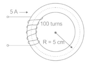
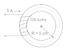
In the magnetic circuit shown below, what is the flux density produced if the relative permeability of the core material under the given condition is 1000?
Detailed Solution for Test: Magnetomotive Force - Question 9

Concept:

Magnetic Field Strength (H): the amount of magnetizing force required to create a certain field density in certain magnetic material per unit length.

The intensity of Magnetization (I): It is induced pole strength developed per unit area inside the magnetic material.

The net Magnetic Field Density (Bnet) inside the magnetic material is due to:

  • Internal factor (I)
  • External factor (H)

∴ Bnet ∝  (H + I)

Bnet  = μ0(H + I) …. (1)

Where μ0 is absolute permeability.

Note: More external factor (H) causes more internal factor (I).

∴ I ∝  H

I = KH …. (2)

And K is the susceptibility of magnetic material.

From equation (1) and equation (2):

Bnet = μ0(H + KH)

Bnet = μ0H(1 + K) …. (3)

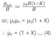
Dividing equation (3) by H on both side

From equation (3) and (4)

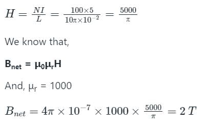
Bnet = μ0μrH

Calculation:

Given Magnetic Circuit,

N = 100
I = 5 A
L = 2πr = 2π × 5 × 10-2 m

From above concept,


Test: Magnetomotive Force - Question 10

If the two conductors carry current in opposite directions, there will be

Detailed Solution for Test: Magnetomotive Force - Question 10

Force Between Current-Carrying Parallel Conductors:

When two current-carrying conductors are parallel to each other, a mechanical force acts on each of the conductors.

This force is the result of each conductor being acted upon by the magnetic field produced by the other.

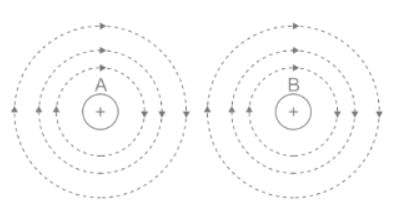
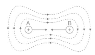
(i) Currents in the Same Direction:

Consider two parallel conductors A and B carrying currents in the same direction and Each conductor will set up its own magnetic field as shown.

It is clear that in the space between A and B, the two fields are in opposition and hence they tend to cancel each other. However, in the space outside A and B,
the two fields assist each other. Hence the resultant field distribution will be as shown,

Since magnetic lines of force behave as stretched elastic cords, the two conductors are attracted towards each other.

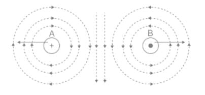
(ii) Currents in the Opposite Direction:

Consider two parallel conductors A and B carrying currents in the opposite direction and Each conductor will set up its own magnetic field as shown.

It is clear that in the space outside A and B, the two fields are in opposition and hence they tend to cancel each other.

However, in the space between A and B, the two fields assist each other.

The lateral pressure between lines of force exerts a force on the conductors tending to push them apart. In other words, the conductors experience a repulsive force.

Conclusion:

If currents are in the same directions, the conductors attract each other; if currents are in opposite directions, the conductors repel each other.

10 videos|45 docs|56 tests
Information about Test: Magnetomotive Force Page
In this test you can find the Exam questions for Test: Magnetomotive Force solved & explained in the simplest way possible. Besides giving Questions and answers for Test: Magnetomotive Force, EduRev gives you an ample number of Online tests for practice

Top Courses for Electrical Engineering (EE)

Download as PDF

Top Courses for Electrical Engineering (EE)