Electrical Engineering (EE) Exam  >  Electrical Engineering (EE) Tests  >  Electrical and Electronic Measurements  >  Test: Measurement of Resistance - 1 - Electrical Engineering (EE) MCQ

Test: Measurement of Resistance - 1 - Electrical Engineering (EE) MCQ


Test Description

10 Questions MCQ Test Electrical and Electronic Measurements - Test: Measurement of Resistance - 1

Test: Measurement of Resistance - 1 for Electrical Engineering (EE) 2024 is part of Electrical and Electronic Measurements preparation. The Test: Measurement of Resistance - 1 questions and answers have been prepared according to the Electrical Engineering (EE) exam syllabus.The Test: Measurement of Resistance - 1 MCQs are made for Electrical Engineering (EE) 2024 Exam. Find important definitions, questions, notes, meanings, examples, exercises, MCQs and online tests for Test: Measurement of Resistance - 1 below.
Solutions of Test: Measurement of Resistance - 1 questions in English are available as part of our Electrical and Electronic Measurements for Electrical Engineering (EE) & Test: Measurement of Resistance - 1 solutions in Hindi for Electrical and Electronic Measurements course. Download more important topics, notes, lectures and mock test series for Electrical Engineering (EE) Exam by signing up for free. Attempt Test: Measurement of Resistance - 1 | 10 questions in 30 minutes | Mock test for Electrical Engineering (EE) preparation | Free important questions MCQ to study Electrical and Electronic Measurements for Electrical Engineering (EE) Exam | Download free PDF with solutions
Test: Measurement of Resistance - 1 - Question 1

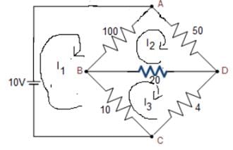
The resistances of the four arms of a Wheatstone bridge are as follows: AB = 100, BC = 10, CD = 4, DA = 50 ohms. A 20-ohm resistance galvanometer is connected between BD. If there is a potential difference of 10 V across the AC, then find the value of the current flowing through the galvanometer.

Detailed Solution for Test: Measurement of Resistance - 1 - Question 1


Applying KVL in loop 1:

Applying KVL in loop 2:

Applying KVL in loop 3:

Solving equations (i), (ii), and (iii), we get:

I1 = 0.276 A

I= 0.184 A

I3 = 0.189 A

The current through the galvanometer is: 

I = 0.189 - 0.184

I = 0.005 A = 5 mA

Test: Measurement of Resistance - 1 - Question 2

Consider the following in context of creeping in energy meter and identify the correct option.

P: The primary reason of creeping is under-compensation for friction.

Q: Creeping may be because of excessive voltage and vibrations.

Detailed Solution for Test: Measurement of Resistance - 1 - Question 2
  • Creeping in energy meters is a phenomenon due to which the Almunium disc rotates due to only voltage applied to the pressure coil and no current flows in the current coil
  • The necessary condition for creeping is that the Pressure coil (PC) must be energized
  • Creeping increases the speed of the disc under low load conditions which increases the meter reading
  • The primary reason for creeping is over-compensation for friction
  • Generally, the friction compensation is so adjusted to give a diving torque required to compensate for the starting friction of the disc
  • Another cause of creeping is the excess voltage, vibrations, and stray magnetic fields across the PC.
  • This develops the excessive friction compensating torque at low load and the disc rotates

Hence we could observe that 

Statement P is incorrect, and statement Q is correct 

1 Crore+ students have signed up on EduRev. Have you? Download the App
Test: Measurement of Resistance - 1 - Question 3

______ eliminates errors due to contacts and ______ in bridge measuring instruments.

Detailed Solution for Test: Measurement of Resistance - 1 - Question 3

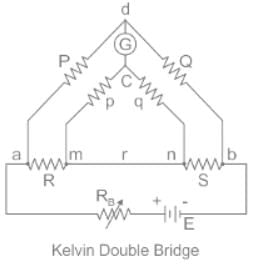
Kelvin's Double bridge:

  • Kelvin Bridge is a modified Wheatstone bridge and provides high accuracy especially in the measurement of low resistance below 1 Ω.
  • The error introduced by the contact/lead resistance is quite large and hence, will give an inaccurate reading if measured through a Wheatstone bridge.
  • In order to avoid this problem, Kelvin's double bridge is used. It is so constructed that the contact resistance will not come into the picture while measuring the value of low resistance.

Advantages:

  • It can measure the resistance value in the range of 0.1 µA to 1.0 A.
  • Power consumption is less.
  • Simple in construction.
  • Sensitivity is high.

Construction:


  • The Kelvin double bridge uses a second set of ratio arms, which is why it is called a "double bridge" and has low resistance arms with four terminal resistors. The first ratio of the arm is P and Q, and the second ratio of the arm is p and q.
  • The Galvanometer is connected between P and p at point d. The point d is placed in the middle of the lead resistance r which is between unknown resistance R and standard resistance S. Thus, the effect of lead resistance r gets eliminated.
Test: Measurement of Resistance - 1 - Question 4

The electrical power to a megger is provided by

Detailed Solution for Test: Measurement of Resistance - 1 - Question 4
  • Megger is a portable instrument to measure high insulation resistances
  • It basically works on the principle of electromagnetic induction
  • The electrical power to a megger is provided by permanent magnet D.C. generator
  • The test voltages are usually of order 500, 1000, or 2500 V are generated by hand driven generator (permanent magnet D.C. generator)
Test: Measurement of Resistance - 1 - Question 5

Kelvin double bridge is best suited for the measurement of

Detailed Solution for Test: Measurement of Resistance - 1 - Question 5

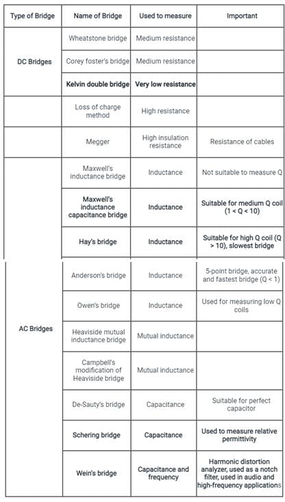
Kelvin's double bridge is used for measuring low values of resistance.

Note:

Test: Measurement of Resistance - 1 - Question 6

A megger is an instrument that gives the reading in:

Detailed Solution for Test: Measurement of Resistance - 1 - Question 6

Megger:

  • Megger is a portable instrument that is used to measure the insulation resistance of the electrical machinery or system.
  • It can be battery operated or mechanically operated (hand crank dc generator) and gives a direct reading in ohms.
  • It basically works on the principle of electromagnetic induction.
  • The electrical power to a megger is provided by a permanent magnet D.C. generator.
  • The operating voltage of a megger is about 50 to 100 V.

Points to remember:

  • Megger is also called an insulation tester because it is used to measure the insulation resistance of underground cables, motor windings, etc.
  • The loss of charge method also used to measure the insulation resistance in MΩ.
Test: Measurement of Resistance - 1 - Question 7

The operation of a Megger is based on which of the following?

Detailed Solution for Test: Measurement of Resistance - 1 - Question 7
  • Megger is a portable instrument to measure high insulation resistances
  • It basically works on the principle of electromagnetic induction
  • The electrical power to a megger is provided by permanent magnet D.C. generator
  • The test voltages are usually of order 500, 1000, or 2500 V are generated by a hand-driven generator (permanent magnet D.C. generator)
  • The operation of a megger is based on moving coil meter
Test: Measurement of Resistance - 1 - Question 8

The test used to locate high resistance faults in low resistance conductor circuit is:

Detailed Solution for Test: Measurement of Resistance - 1 - Question 8

Murray loop test is the most common method for locating high resistance faults in low resistance conductor circuit. It employs the principle of Wheatstone bridge to determine the fault location.

Important Points:

  • Hopkinson’s Test is a method of determining the efficiency of a DC machine. It is a full load test and it requires two identical machines which are coupled together. One of the two machines is operated as a generator and the other is operated as a motor to drive the generator. It is also called a back-to-back test or regenerative test.
  • Open circuit test is done on the transformer to determine core losses in transformer and the parameters of the shunt branch of the equivalent circuit of the transformer. This test is done on LV side while keeping HV side of the transformer open-circuited. 
Test: Measurement of Resistance - 1 - Question 9

In a megger, controlling torque is provided by

Detailed Solution for Test: Measurement of Resistance - 1 - Question 9

A Deflecting and Control coil is connected parallel to the generator, mounted at right angle to each other and maintain polarities in such a way to produced torque in opposite direction. Hence in a megger, controlling torque is provided by coil.

Test: Measurement of Resistance - 1 - Question 10

For the measurement of high resistances following methods are used:

1. Loss of Charge Method

2. Direct Deflection Method

3. Substitution Method

Which of the following is/are correct?

Detailed Solution for Test: Measurement of Resistance - 1 - Question 10

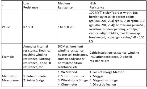
The Measurement of Resistance according to classification is shown below:

3 videos|39 docs|22 tests
Information about Test: Measurement of Resistance - 1 Page
In this test you can find the Exam questions for Test: Measurement of Resistance - 1 solved & explained in the simplest way possible. Besides giving Questions and answers for Test: Measurement of Resistance - 1, EduRev gives you an ample number of Online tests for practice

Top Courses for Electrical Engineering (EE)

Download as PDF

Top Courses for Electrical Engineering (EE)