Electrical Engineering (EE) Exam  >  Electrical Engineering (EE) Tests  >  Power Systems  >  Test: Power Factor Correction - Electrical Engineering (EE) MCQ

Test: Power Factor Correction - Electrical Engineering (EE) MCQ


Test Description

10 Questions MCQ Test Power Systems - Test: Power Factor Correction

Test: Power Factor Correction for Electrical Engineering (EE) 2024 is part of Power Systems preparation. The Test: Power Factor Correction questions and answers have been prepared according to the Electrical Engineering (EE) exam syllabus.The Test: Power Factor Correction MCQs are made for Electrical Engineering (EE) 2024 Exam. Find important definitions, questions, notes, meanings, examples, exercises, MCQs and online tests for Test: Power Factor Correction below.
Solutions of Test: Power Factor Correction questions in English are available as part of our Power Systems for Electrical Engineering (EE) & Test: Power Factor Correction solutions in Hindi for Power Systems course. Download more important topics, notes, lectures and mock test series for Electrical Engineering (EE) Exam by signing up for free. Attempt Test: Power Factor Correction | 10 questions in 20 minutes | Mock test for Electrical Engineering (EE) preparation | Free important questions MCQ to study Power Systems for Electrical Engineering (EE) Exam | Download free PDF with solutions
Test: Power Factor Correction - Question 1

Which of the following methods is NOT used in the improvement of the power factor of a network?

Detailed Solution for Test: Power Factor Correction - Question 1

Power factor:

  • The overall power factor is defined as the cosine of the angle between the phase voltage and phase current. 
  • In AC circuits, the power factor is also defined as the ratio of the real power flowing to the load to the apparent power in the circuit. 
    Hence power factor can be defined as watts to volt-amperes.
  • It is also defined as the ratio of resistance to the impedance of the circuit.
  • So that by increasing resistance, the power factor can be increased. But due to power losses practically it is not used.
  • Typically capacitor is used for power factor improvement purposes.

Disadvantages of low power factor:

  • Large kVA rating of the equipment
  • Greater conductor size
  • Large copper losses
  • Poor voltage regulation
  • The reduced handling capacity of the system
  • Cost of station and distribution equipment is more for a given load

Causes of low power factor:

  • Most of the AC motors are of induction type (1φ and 3φ induction motors) which have a low lagging power factor
  • These motors work at a power factor which is extremely small on light load (0.2 to 0.3) and rises to 0.8 or 0.9 at full load
  • Arc lamps, electric discharge lamps and industrial heating furnaces operate at a low lagging power factor
  • The load on the power system is varying; being high during morning and evening and low at other times
  • During low load period, the supply voltage is increased which increases the magnetisation current, this results in the decreased power factor

Low power factor can be avoided by:

  • Using synchronous motors instead of induction motors
  • Using high-speed induction motors to low-speed machines
  • Not operating induction motors at less than the rated output
  • By using the following equipment
  1. Static capacitors
  2. Synchronous condenser
  3. Phase advancer
  4. Use of high power factor equipment

High inductive element in series with the load is not used for the power factor improvement.

Test: Power Factor Correction - Question 2

Which device is employed to reduce the power factor in the case of the leading power factor in the transmission line?

1. Synchronous condenser

2. SVC

3. Reactor

Detailed Solution for Test: Power Factor Correction - Question 2

Ferranti effect:

  • In the case of a no-load in the transmission line, the voltage at the receiving end becomes greater than the sending end. This condition is known as the Ferranti effect.
  • Under such cases, the power factor of the line becomes leading in nature.
  • In such cases, a synchronous reactor is connected to the receiving end.
  • It absorbs excess reactive power available in the line, thus decreasing the overvoltage condition.
1 Crore+ students have signed up on EduRev. Have you? Download the App
Test: Power Factor Correction - Question 3

Power factor can be improved by installing a device in parallel with load which has _______.

Detailed Solution for Test: Power Factor Correction - Question 3

The power factor can be improved by installing a device in parallel with a load that has ​leading reactive power.

Low power factor can be avoided by:

  • Using synchronous motors instead of induction motors
  • Using high-speed induction motors to low-speed machines
  • Not operating induction motors at less than the rated output
  • By using the following equipment
  1. Static capacitors
  2. Synchronous condenser
  3. Phase advancer

Causes of low power factor:

  • Most of the AC motors are of induction type (1φ and 3φ induction motors) which have a low lagging power factor
  • These motors work at a power factor which is extremely small on light load (0.2 to 0.3) and rises to 0.8 or 0.9 at full load
  • Arc lamps, electric discharge lamps and industrial heating furnaces operate at a low lagging power factor
  • The load on the power system is varying; being high during morning and evening and low at other times
  • During low load period, the supply voltage is increased which increases the magnetisation current, this results in the decreased power factor
Test: Power Factor Correction - Question 4

Which of the following leads to a low voltage and a low power factor?

Detailed Solution for Test: Power Factor Correction - Question 4
  • Harmonics can be best described as the shape or characteristics of a voltage or current waveform relative to its fundamental frequency
  • The ideal power source for all power systems is smooth sinusoidal waves
  • These perfect sinewaves do not contain harmonics
  • When waveforms deviate from a sinewave shape, they contain harmonics
  • These current harmonics distort the voltage waveform and create distortion in the power system which can cause many problems
  • In power generation, harmonics leads to low voltage and low power factor generation in the power system
Test: Power Factor Correction - Question 5

How does the synchronous condenser work under light loads?

Detailed Solution for Test: Power Factor Correction - Question 5

Synchronous condenser:

  • A synchronous motor takes a leading current when over-excited and, therefore, behaves as a capacitor
  • An over-excited synchronous motor running on no load is known as synchronous condenser
  • When such a machine is connected in parallel with the supply, it takes a leading current which partly neutralises the lagging reactive component of the load
  • It works as a VAR generator.
  • Thus, the power factor is improved

Advantages:

  • By varying the field excitation, the magnitude of current drawn by the motor can be changed by any amount, this helps in achieving stepless control of power factor
  • The motor windings have high thermal stability to short circuit currents
  • The faults can be removed easily

Disadvantages:

  • There are considerable losses in the motor
  • The maintenance cost is high
  • It produces noise
  • Except in sizes above 500 kVA, the cost is greater than that of static capacitors of the same rating
  • As a synchronous motor has no self-starting torque, therefore, an auxiliary equipment has to be provided for this purpose
Test: Power Factor Correction - Question 6

An alternator is supplying a load of 300 kW at 0.6 p.f. lagging. If the power factor is raised to unity, how many more kilowatts can alternator supply for the same kVA loading?

Detailed Solution for Test: Power Factor Correction - Question 6

P = S cos ɸ

P = 300 kW, cos ɸ = 0.6

S = 300/0.6 = 500 kVA

Now, cos ɸ = 1, S = 500 kVA

P = 500 × 1 = 500 kW

More kilo watts can alternator supply for the same kVA loading = 500 – 300 = 200 kW

Test: Power Factor Correction - Question 7

Which one of the following statements is incorrect about shunt capacitors?

Detailed Solution for Test: Power Factor Correction - Question 7

Static Shunt Capacitor:

  • The power factor can be improved by connecting capacitors in parallel with the equipment operating at a lagging power factor.
  • It is always desired to commission a capacitor bank nearer to reactive load, this makes the transmission of reactive kVARr removed from a greater part of the network
  • Shunt capacitors operate at leading pf (like No-load over-excited synchronous motors)i.e. they consume leading VARs by delivering the lagging VARs.
  • Reactive power supplied by capacitor bank is given by the formula: 

Advantages:
(i) They have low losses.
(ii) They require little maintenance as there are no rotating parts.
(iii) They can be easily installed as they are light and require no foundation.
(iv) They can work under ordinary atmospheric conditions.

Disadvantages:
(i) They have short service life ranging from 8 to 10 years.
(ii) They are easily damaged if the voltage exceeds the rated value.
(iii) Once the capacitors are damaged, their repair is uneconomical

Test: Power Factor Correction - Question 8

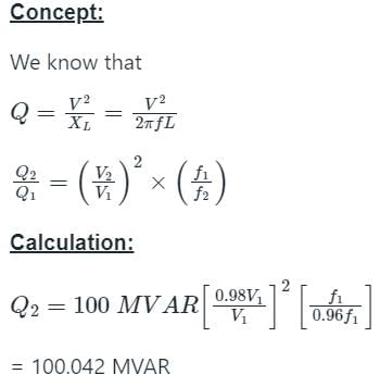
A shunt reactor of 100 MVAR is operated at 98% of its rated voltage and at 96% of its rated frequency. The reactive power absorbed by the reactor is

Detailed Solution for Test: Power Factor Correction - Question 8

Test: Power Factor Correction - Question 9

A single-phase motor takes 50 A at a power factor angle of 30° lagging from a 250-V, 50-Hz AC supply. What value of capacitance must a shunting capacitor have to raise the power factor to unity?

Detailed Solution for Test: Power Factor Correction - Question 9

Concept:

Real power for single-phase P = VI cosθ

Reactive power for single-phase Q = VI sinθ

For purely capacitive circuit Q = v2ω c

Note: To suppress the inductive effect of load, we add purely capacitive load across load.

Calculation:

Given V = 250 volt

I = 50 amp

θ = 30°

ω = 2 × π × 50 = 314

Reactive power = 250 × 50 × sin30° = 6250 VAr

For unity power factor, we add capacitance across load

V2ωC = 6250 VAr

⇒ 2502 × 314 × C = 6250 VAr

⇒ C = 318.3 μF

Test: Power Factor Correction - Question 10

Capacitors with automatic power factor controller, when installed in a plant:

Detailed Solution for Test: Power Factor Correction - Question 10
  • Capacitors with automatic power factor controller, when installed in a plant, reduce the reactive power drawn from the grid.
  • Capacitors are used to improve power factor by providing reactive power to counteract the reactive power demand of inductive loads in a plant.
  • The automatic power factor controller monitors the power factor and voltage of the system and controls the switching of capacitors to maintain a desired power factor level.
  • By doing so, it helps in reducing the amount of reactive power drawn from the grid, which in turn reduces the overall demand for reactive power and improves the efficiency of the system.
21 videos|67 docs|45 tests
Information about Test: Power Factor Correction Page
In this test you can find the Exam questions for Test: Power Factor Correction solved & explained in the simplest way possible. Besides giving Questions and answers for Test: Power Factor Correction, EduRev gives you an ample number of Online tests for practice

Top Courses for Electrical Engineering (EE)

21 videos|67 docs|45 tests
Download as PDF

Top Courses for Electrical Engineering (EE)