Electrical Engineering (EE) Exam  >  Electrical Engineering (EE) Tests  >  Analog and Digital Electronics  >  Test: Priority Encoders - Electrical Engineering (EE) MCQ

Test: Priority Encoders - Electrical Engineering (EE) MCQ


Test Description

10 Questions MCQ Test Analog and Digital Electronics - Test: Priority Encoders

Test: Priority Encoders for Electrical Engineering (EE) 2024 is part of Analog and Digital Electronics preparation. The Test: Priority Encoders questions and answers have been prepared according to the Electrical Engineering (EE) exam syllabus.The Test: Priority Encoders MCQs are made for Electrical Engineering (EE) 2024 Exam. Find important definitions, questions, notes, meanings, examples, exercises, MCQs and online tests for Test: Priority Encoders below.
Solutions of Test: Priority Encoders questions in English are available as part of our Analog and Digital Electronics for Electrical Engineering (EE) & Test: Priority Encoders solutions in Hindi for Analog and Digital Electronics course. Download more important topics, notes, lectures and mock test series for Electrical Engineering (EE) Exam by signing up for free. Attempt Test: Priority Encoders | 10 questions in 20 minutes | Mock test for Electrical Engineering (EE) preparation | Free important questions MCQ to study Analog and Digital Electronics for Electrical Engineering (EE) Exam | Download free PDF with solutions
Test: Priority Encoders - Question 1

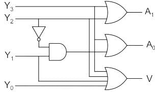
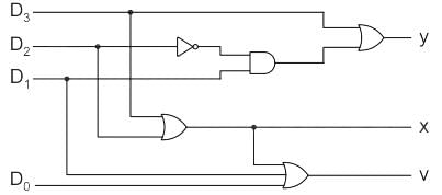
The logic shown in the given figure works as:

Detailed Solution for Test: Priority Encoders - Question 1

Priority encoder:-

If more than one input is high then encoder produce an output which may not be correct to overcome this we use priority encoder.

We considered one more output, V in order to know, whether the code available at outputs is valid or not.

If at least one input of the encoder is ‘1’, then the code available at outputs is a valid one. In this case, the output, V will be equal to 1.

If all the inputs of encoder are ‘0’, then the code available at outputs is not a valid one. In this case, the output, V will be equal to 0.

Analysis:-

Logic shown in given figure will work as

Priority encoder (4 × 2)

Inputs = D3, D2, D1, D0

Output:

y = D3 + D2’ D1

X = D3 + D2

V = D3 + D2 + D1 + D0

Test: Priority Encoders - Question 2

Consider the output A and B with I0, I1, I2 and I3 as input and ‘A’ and ‘B’ as output,

A = I2 + I3

B = I̅I+ I3

The above circuit is:

Detailed Solution for Test: Priority Encoders - Question 2

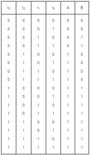
A 4 to 2 Priority Encoder takes 4 input bits and produces 2 Output bits. The truth Table of a 4 to 2 Priority Encoder is as shown:

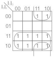
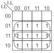
We use Karnaugh Map to minimize the logic for B as shown:

B = I̅2I1 + I3

Similarly the expression for A in obtained using K-map as shown:

A = I2 + I3

So, the given circuit is a priority Encoder only.

1 Crore+ students have signed up on EduRev. Have you? Download the App
Test: Priority Encoders - Question 3

The below circuit is ______.

Detailed Solution for Test: Priority Encoders - Question 3

For a simple decimal → BCD encoder, we find A is true for 1, 3, 5, 7, 9

where A → LSB of BCD code is:

A = 1 + 3 + 5 + 7 + 9B

= 2 + 3 + 6 + 7C

= 4 + 5 + 6 + 7 MSB D = 8 + 9

Now, with 7 given priority over 0, 2 & 5, the logic will be A is HIGH if 1 is HIGH & 2, 4, 6, 8 are LOW

A is HIGH if 3 is HIGH & 4, 6, 8 are LOW

A is HIGH if 5 is HIGH & 6, 8 are LOW

A is HIGH if 7 is HIGH & 8 is LOW

A is HIGH if 9 is HIGH

So, logic equation

Test: Priority Encoders - Question 4

The truth table of logic function F is given below
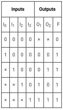
If in the truth table F = 1 if and only if the input is valid. What function does the truth table represent?

Detailed Solution for Test: Priority Encoders - Question 4

Since the given truth table has more than one output and the number of outputs is less than number of inputs, the given logic function represents priority encoder. It checks the highest priority high bit encountered in input bits.

Test: Priority Encoders - Question 5

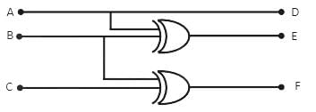
For input A, B, C and output D, E, F Identify the circuit

Detailed Solution for Test: Priority Encoders - Question 5

The above circuit is none of the above mentioned three circuits, viz, 3 bit priority generator, full subtractor or 3 bit priority encoder.

Test: Priority Encoders - Question 6

Can an encoder be called a multiplexer?

Detailed Solution for Test: Priority Encoders - Question 6

A multiplexer or MUX is a combination circuit that contains more than one input line, one output line and more than one selection line. Whereas, an encoder is also considered a type of multiplexer but without a single output line and without any selection lines.

Test: Priority Encoders - Question 7

If two inputs are active on a priority encoder, which will be coded on the output?

Detailed Solution for Test: Priority Encoders - Question 7

An encoder is a combinational circuit encoding the information of 2n input lines to n output lines, thus producing the binary equivalent of the input. If two inputs are active on a priority encoder, the input of higher value will be coded in the output.

Test: Priority Encoders - Question 8

What is a four-line to two-line priority encoder with active HIGH inputs and outputs, with priority assigned to the higher-order data input line?

Detailed Solution for Test: Priority Encoders - Question 8

Here, X represents the priority encoder output.

Y represents the valid output corresponding to the highest order active input.

  • In a four-line to two-line priority encoder, the goal is to encode the highest order active input among four lines into a two-bit output.
  • X = D2+D3
  • This equation means that the output X is active (HIGH) when either D2 or D3 is active.
  • It indicates the encoding of the higher-priority input.
  • Y = D12+D3
  • Y is the two-bit output. It is formed by combining D1D2 if both D1 and D2 are active, or by using D3 if Dis active alone. This represents the highest-order active input.
  • X = D2+D3  
  • Y = D12+D3

Here, option 1 is correct.

Test: Priority Encoders - Question 9

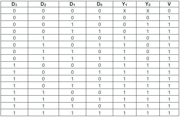
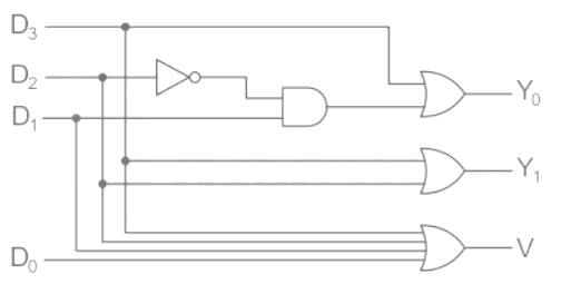
Determine the type of circuit shown in figure below consider y0 and y1 to be don’t care condition when all inputs are zero.
Detailed Solution for Test: Priority Encoders - Question 9

From the given logic circuit,

V = D0 + D1 + D2 + D3

y0 = D3 + D12

y1 = D2 + D3

The truth table for the given logic circuit is given below.

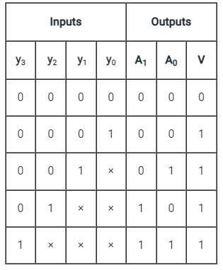
From the above truth table, it is clear that When D3 = 1, the output (Y1 Y0) = (11)2 = (3)10 irrespective of other inputs.

For D3 = 0 and D2 = 1, the output Y1 Y0 = (10)2 = (2)10 irrespective of other inputs.

For D3 = D2 = 0 and D1 = 1, the output

Y1Y0 = (01)2 = (1)10 irrespective of other inputs.

The output will be Y1Y0 = (00)2 = (0)10 only

When D3 = D2 = D1 = 0 and D0 = 1.

Therefore, the given logic circuit is a priority encoder with a priority order D3 > D2 > D1 > D0

Test: Priority Encoders - Question 10

In a 8-bit ripple carry adder using identical full adders, each full adder takes 34 ns for computing sum. If the time taken for 8-bit addition is 90 ns, find time taken by each full adder to find carry

Detailed Solution for Test: Priority Encoders - Question 10

Formula:

The total time taken by the for ‘n’ bit ripple carry adder is

T= (n – 1) tc + Maximum(tc, ts)

tc = delay for carry through a single flip flop.

ts delay for sum

Data:

Each full adder takes 34 ns for computing

From this, Maximum(tc, ts) = ts = 34 ns

Td = 90 ns.

n = 8

Calculation:

T= (n – 1) tc + Maximum(tc, ts)

90 = (8 – 1)tc + 34

7tn = 56 ns.

∴ tn = 8 ns.

Time taken by each full adder to find carry is 8 ns.
Important Point:

If Maximum(tc, ts) = tc then answer is 11.25 which is not in option

∴ Maximum(tc, ts) has to be ts

137 videos|143 docs|71 tests
Information about Test: Priority Encoders Page
In this test you can find the Exam questions for Test: Priority Encoders solved & explained in the simplest way possible. Besides giving Questions and answers for Test: Priority Encoders, EduRev gives you an ample number of Online tests for practice

Top Courses for Electrical Engineering (EE)

137 videos|143 docs|71 tests
Download as PDF

Top Courses for Electrical Engineering (EE)