Electrical Engineering (EE) Exam > Electrical Engineering (EE) Tests > Test: Resonance - 2 - Electrical Engineering (EE) MCQ
Test: Resonance - 2 - Electrical Engineering (EE) MCQ
Test Description
10 Questions MCQ Test - Test: Resonance - 2
Test: Resonance - 2 for Electrical Engineering (EE) 2025 is part of Electrical Engineering (EE) preparation. The Test: Resonance - 2 questions and answers have been prepared
according to the Electrical Engineering (EE) exam syllabus.The Test: Resonance - 2 MCQs are made for Electrical Engineering (EE) 2025 Exam.
Find important definitions, questions, notes, meanings, examples, exercises, MCQs and online tests for Test: Resonance - 2 below.
Solutions of Test: Resonance - 2 questions in English are available as part of our course for Electrical Engineering (EE) & Test: Resonance - 2 solutions in
Hindi for Electrical Engineering (EE) course.
Download more important topics, notes, lectures and mock test series for Electrical Engineering (EE) Exam by signing up for free. Attempt Test: Resonance - 2 | 10 questions in 30 minutes | Mock test for Electrical Engineering (EE) preparation | Free important questions MCQ to study for Electrical Engineering (EE) Exam | Download free PDF with solutions
Detailed Solution for Test: Resonance - 2 - Question 1
Test: Resonance - 2 - Question 2
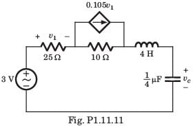
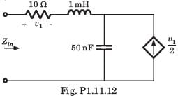
For the circuit shown in fig. P1.1.11 resonant frequency fo is

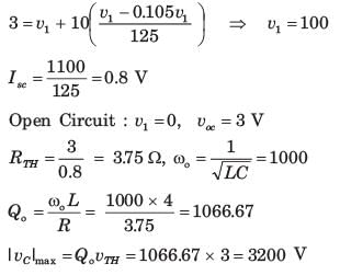
Detailed Solution for Test: Resonance - 2 - Question 2
Test: Resonance - 2 - Question 3
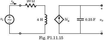
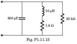
For the circuit shown in fig. P1.11.13 the resonant frequency f0 is

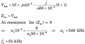
Detailed Solution for Test: Resonance - 2 - Question 3
Test: Resonance - 2 - Question 4
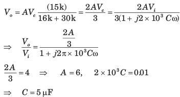
The network function of circuit shown in fig.P1.11.14 is
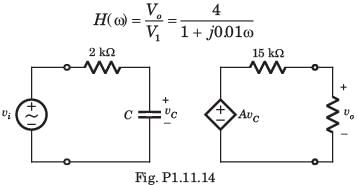
The value of the C and A is
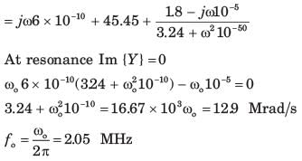
Detailed Solution for Test: Resonance - 2 - Question 4
Detailed Solution for Test: Resonance - 2 - Question 5
Detailed Solution for Test: Resonance - 2 - Question 6
Test: Resonance - 2 - Question 7
The value of input frequency is required to cause a gain equal to 1.5. The value is
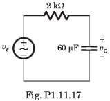
Detailed Solution for Test: Resonance - 2 - Question 7
Test: Resonance - 2 - Question 8
In the circuit of fig. P1.11.18 phase shift equal to -450 is required at frequency ω = 20 rad/s . The value of R is
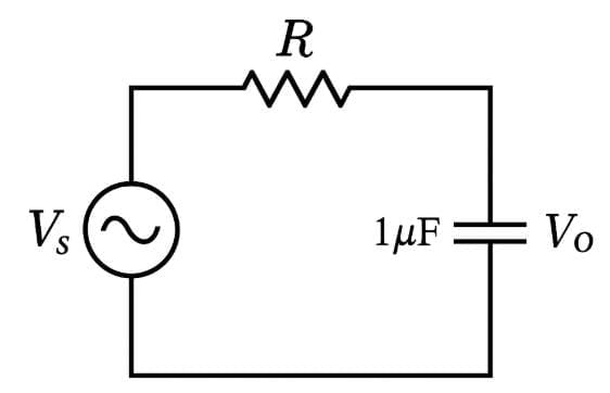
Detailed Solution for Test: Resonance - 2 - Question 8
Test: Resonance - 2 - Question 9
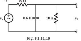
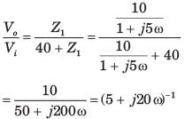
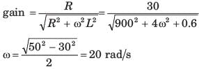
For the circuit of fig. P1.11.19 the input frequency is adjusted until the gain is equal to 0.6. The value of the frequency is
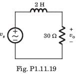
Detailed Solution for Test: Resonance - 2 - Question 9
Test: Resonance - 2 - Question 10
Bode diagram of the network function Vo/Vs for the circuit of fig. P1.11.30 is
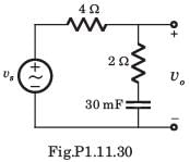
Detailed Solution for Test: Resonance - 2 - Question 10
Information about Test: Resonance - 2 Page
In this test you can find the Exam questions for Test: Resonance - 2 solved & explained in the simplest way possible.
Besides giving Questions and answers for Test: Resonance - 2, EduRev gives you an ample number of Online tests for practice
Download as PDF


