Electronics and Communication Engineering (ECE) Exam  >  Electronics and Communication Engineering (ECE) Tests  >  Digital Circuits  >  Test: Sequential Circuits - Electronics and Communication Engineering (ECE) MCQ

Test: Sequential Circuits - Electronics and Communication Engineering (ECE) MCQ


Test Description

10 Questions MCQ Test Digital Circuits - Test: Sequential Circuits

Test: Sequential Circuits for Electronics and Communication Engineering (ECE) 2024 is part of Digital Circuits preparation. The Test: Sequential Circuits questions and answers have been prepared according to the Electronics and Communication Engineering (ECE) exam syllabus.The Test: Sequential Circuits MCQs are made for Electronics and Communication Engineering (ECE) 2024 Exam. Find important definitions, questions, notes, meanings, examples, exercises, MCQs and online tests for Test: Sequential Circuits below.
Solutions of Test: Sequential Circuits questions in English are available as part of our Digital Circuits for Electronics and Communication Engineering (ECE) & Test: Sequential Circuits solutions in Hindi for Digital Circuits course. Download more important topics, notes, lectures and mock test series for Electronics and Communication Engineering (ECE) Exam by signing up for free. Attempt Test: Sequential Circuits | 10 questions in 30 minutes | Mock test for Electronics and Communication Engineering (ECE) preparation | Free important questions MCQ to study Digital Circuits for Electronics and Communication Engineering (ECE) Exam | Download free PDF with solutions
Test: Sequential Circuits - Question 1

The expression for MOD number for a ripple counter with N flip-flops is

Detailed Solution for Test: Sequential Circuits - Question 1

Ripple Counter: For a ripple counter if the number of flip flops is 'n' then total states are 2n and MOD is 2n

BCD Counter:
A BCD counter counts 10 states from 0 to 9 
It is MOD 10 counter 
Number of flips required 4 

Ring counter: A n bit ring counter counts n states and mod is "n"

Johnson Counter: A n bit Johnson ring counter has 2n states and the mod is 2n

Test: Sequential Circuits - Question 2

Calculate the maximum clock frequency at which a 4-bit asynchronous counter can work reliably. Assume the propagation delay of each flip-flop to be 40 ns and the width of the strobe pulse to be 20 ns.

Detailed Solution for Test: Sequential Circuits - Question 2

Concept:

  • Lockout free condition: If a counter from an unused state enters one of the used states then the counter is called lock-out free. While taking any unused state as the initial state if the next state comes out to be a used state, the counter is said to be lockout free.
  • Synchronous counter: A counter in which all the flip-flops are triggered with the same clock pulse. In such counters, if the propagation delay of one flip-flop is tf, then the propagation delay for the whole counter will also be tf
  • Asynchronous counter: A counter in which all the flip flops are not triggered by the same clock pulse. In such counters, total propagation delay will be equal to the sum of propagation delay for all flip flops.

Calculation:
Given that, propagation delay of each flip-flop = 40 ns
Width of the strobe pulse = 20 ns
Total propagation delay = 40 × 4 + 20 = 180 ns
Maximum clock frequency 

1 Crore+ students have signed up on EduRev. Have you? Download the App
Test: Sequential Circuits - Question 3

A cascade of three identical modulo-5 counters has an overall modulus of

Detailed Solution for Test: Sequential Circuits - Question 3

Concept: Overall modulus of a cascaded system is the product of their individual modules.

For example: A counter of modulus p, modulus q, and modulus r is cascaded, then the modulus of the overall counter is p × q × r

Calculation:
Given, 
The modulus of all three counters is 5
Then the overall modulus = 5 × 5 × 5 = 125

Test: Sequential Circuits - Question 4

A 6 bit counter is used to count from 0, 1, 2, ......n. The value of n is _____

Detailed Solution for Test: Sequential Circuits - Question 4

Concept: A n bit counter has 2n states and can count from 0 to 2n-1

Application:
Given:
n = 6
so it will count from 0 to 26 - 1
= 0 to 63

Test: Sequential Circuits - Question 5

Race-around condition occurs in

Detailed Solution for Test: Sequential Circuits - Question 5

Race around condition:
For JK flip-flop if J, K, and Clock are equal to 1 the state of flip-flop keeps on toggling which leads to uncertainty in determining the output of the flip-flop. This problem is called Race around the condition.
This can be eliminated by using the following methods.

  • Increasing the delay of flip-flop
  • Use of edge-triggered flip-flop
  • Use of master-slave JK flip flop

The Master-slave configuration is used in a flipflop to eliminate the race around condition but not to store two bits of information.

Test: Sequential Circuits - Question 6

An eight-bit binary ripple UP counter with a modulus of 256 is holding the count 01111111. What will be the count after 135 clock pulses?

Detailed Solution for Test: Sequential Circuits - Question 6

01111111 → 127
After 135 clock cycles, we will get
127 + 135 = 262
∴ The total number of clock pulses will be 262
As the modulus is 256,
After 256 clock pulses, the sequence will repeat.
262 = 256 + 6
∴ 00 00 00 00
257 → 00 00 00 01
258 → 00 00 00 10
259 → 00 00 00 11
260 → 00 00 01 00
261 → 00 00 01 01
262 → 00 00 01 10

Test: Sequential Circuits - Question 7

Which of the following is not a sequential circuit?

Detailed Solution for Test: Sequential Circuits - Question 7
  • Combinational logic is a type of digital logic that is implemented by Boolean circuits, where the output is a pure function of the present input only.
  • Sequential logic is a type of digital logic in which the output depends not only on the present input but also on the history of the output.
  • Sequential logic has memory while combinational logic does not.
  • Flip-flop, counter, and shift registers are sequential circuits whereas multiplexer, decoder, and encoder act like combinational circuits.
Test: Sequential Circuits - Question 8

In a D flip flop, if the present state is 1, what will be the next state of the output at the complement end?

Detailed Solution for Test: Sequential Circuits - Question 8

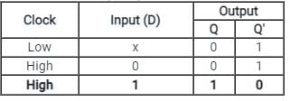
Truth table of D Flip-Flop:

  • The D(Data) is the input state for the D flip-flop.
  • The Q and Q’ represents the Normal output and Complementary or Inverted output states respectively of the flip-flop.
  • According to the table, based on the inputs the output changes its state. But, the important thing to consider is all these can occur only in the presence of the clock signal. 
  • As shown in the truth table of the D flip flop given above, if the present state is '1', then '0' will be the next state of the output at the complement end.
Test: Sequential Circuits - Question 9

A frequency counter needs to measure a frequency of 30 Hz. If the gating time is 2 seconds then determine how many times the trigger level has been crossed?

Detailed Solution for Test: Sequential Circuits - Question 9

Concept:
digital frequency counters that use a direct counting approach count the number of times the input signal crosses a given trigger voltage (and in a given direction, e.g. moving from negative to positive) in a given time. This time is known as gate time.
The frequency is equal to the number of crossings of the trigger level in one second. Therefore

Calculation:
Given;
Gate time = 2 sec
Frequency = 30 Hz
Then;

∴ Trigger level crossing = frequency x gate time = 30 x 2 = 60

Test: Sequential Circuits - Question 10

A sequence detector is designed to detect precisely 3 digital inputs, with overlapping sequences detectable. For the sequence (1,0,1) and input data (1,1,0,1,0,0,1,1,0,1,0,1,1,0), what is the output of this detector?

Detailed Solution for Test: Sequential Circuits - Question 10

A sequence detector is a sequential circuit that outputs 1 when a particular pattern of bits sequentially arrives at its data input.
Given input data = 1,1,0,1,0,0,1,1,0,1,0,1,1,0
Overlapping sequences detectable.
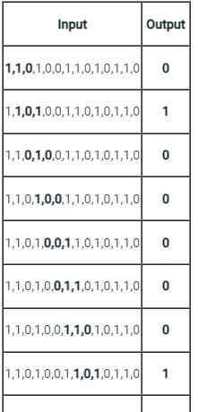
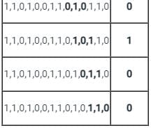
The below table shows the output for each sequence.


The output = 0,1,0,0,0,0,0,1,0,1,0,0

6 videos|76 docs|52 tests
Information about Test: Sequential Circuits Page
In this test you can find the Exam questions for Test: Sequential Circuits solved & explained in the simplest way possible. Besides giving Questions and answers for Test: Sequential Circuits, EduRev gives you an ample number of Online tests for practice

Top Courses for Electronics and Communication Engineering (ECE)

6 videos|76 docs|52 tests
Download as PDF

Top Courses for Electronics and Communication Engineering (ECE)