Test: Shear Force & Bending Moment - 3 - Civil Engineering (CE) MCQ
10 Questions MCQ Test - Test: Shear Force & Bending Moment - 3
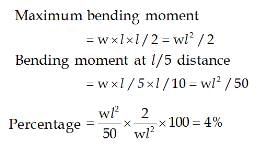
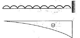
In figure the maximum bending moment at the fixed end of the cantilever caused by the UDL is M.

The bending moment at a section //5 from the free end is

The bending moment at a section //5 from the free end is
The shear force along the beam shown in the figure is


The correct shear force diagram for the beam shown in the figure is


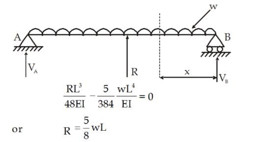
A simply supported beam of span 'L' carrying a UDL of w per unit length. If the beam is propped at its centre then in bending moment diagram, the bending moment is zero at a distance of
The beam shown in the given figure has a design value of bending moment of
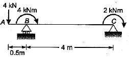
A cantilever beam is subjected to moments as shown in the given figure. The BM diagram for the beam will be

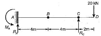
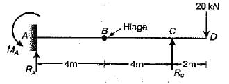
The fixed end moment MA of the beam shown in the given figure is
A simply supported beam with equal overhang ori both sides is loaded as shown in the figure. If the bending moment at mid-span is zero, then the percentage overhang on each side will be

A propped cantilever beam shown in the figure given is having interna! hinge at its mid-span. Which one of the following is the shape of bending moment diagram for the given loading?

In the case of l-section, the web resists mainly


