Mechanical Engineering Exam  >  Mechanical Engineering Tests  >  Strength of Materials (SOM)  >   Test: Simple Stress & Strain Level - 3 - Mechanical Engineering MCQ

Test: Simple Stress & Strain Level - 3 - Mechanical Engineering MCQ


Test Description

20 Questions MCQ Test Strength of Materials (SOM) - Test: Simple Stress & Strain Level - 3

Test: Simple Stress & Strain Level - 3 for Mechanical Engineering 2024 is part of Strength of Materials (SOM) preparation. The Test: Simple Stress & Strain Level - 3 questions and answers have been prepared according to the Mechanical Engineering exam syllabus.The Test: Simple Stress & Strain Level - 3 MCQs are made for Mechanical Engineering 2024 Exam. Find important definitions, questions, notes, meanings, examples, exercises, MCQs and online tests for Test: Simple Stress & Strain Level - 3 below.
Solutions of Test: Simple Stress & Strain Level - 3 questions in English are available as part of our Strength of Materials (SOM) for Mechanical Engineering & Test: Simple Stress & Strain Level - 3 solutions in Hindi for Strength of Materials (SOM) course. Download more important topics, notes, lectures and mock test series for Mechanical Engineering Exam by signing up for free. Attempt Test: Simple Stress & Strain Level - 3 | 20 questions in 60 minutes | Mock test for Mechanical Engineering preparation | Free important questions MCQ to study Strength of Materials (SOM) for Mechanical Engineering Exam | Download free PDF with solutions
Test: Simple Stress & Strain Level - 3 - Question 1

Consider the following statements Modulus of rigidity and bulk modulus of a material are found to be 60 GPa and 140 GPa respectively. Then

1. elasticity modulus is nearly 200 GPa

2. Poisson’s ratio is nearly 0.3

3. elasticity modulus is nearly 158 GPa

4. Poisson’s ratio is nearly 0.25

Which of these statements are correct?

Detailed Solution for Test: Simple Stress & Strain Level - 3 - Question 1
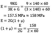
G = 60 GPa

K = 140 GPa

μ = 0.31 ≈ 0.3 Statement 2 and 3 are correct.

Test: Simple Stress & Strain Level - 3 - Question 2

In the arrangement as shown in the figure, the stepped steel bar ABC is loaded by a load P. The material has Young’s modulus E = 200 GPa and the two portions AB and BC have area of cross section 1cm2 and 2cm2 respectively. The magnitude of load P required to fill up the gap of 0.75mm is

Detailed Solution for Test: Simple Stress & Strain Level - 3 - Question 2

E = 200 GPa = 200 x 103 MPa

AAB = 1 cm2 = 100 mm2

ABC = 2 cm2 = 200 mm2

Gap(δ) = 0.75 mm

There will be no deformation in BC so,

δAB = δ

P = 75 x 200 = 15 x 103N = 15 kN

1 Crore+ students have signed up on EduRev. Have you? Download the App
Test: Simple Stress & Strain Level - 3 - Question 3

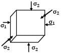
An elastic material of Young’s modulus E and Poisson’s ratio v is subjected to a compressive stress of σ1 in the longitudinal direction.

Suitable lateral compressive stress σ2 is also applied along the other two lateral directions to limit the net strain in each of the lateral directions to half of the magnitude that would be under σ1 acting alone. The magnitude of σ2 is

Detailed Solution for Test: Simple Stress & Strain Level - 3 - Question 3
σ1 is acting along longitudinal direction

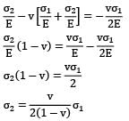
Strain in lateral direction

Strain in lateral direction when σ1 acts alone.

Test: Simple Stress & Strain Level - 3 - Question 4

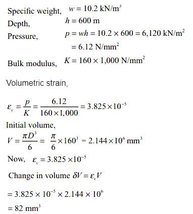
A spherical ball of a material of a diameter of 160mm goes down to a depth of 600 m in sea water. If the specific weight of sea water is 10.2kN/m3 and the bulk modulus of the material of the ball is 160kN/mm2, determine the change in volume of ball. 

Detailed Solution for Test: Simple Stress & Strain Level - 3 - Question 4

Test: Simple Stress & Strain Level - 3 - Question 5

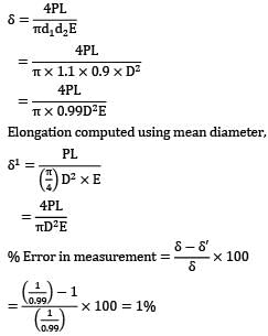
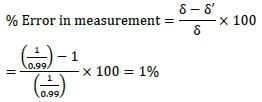
A bar of length L tapers uniformly from diameter 1.1 D at one end to 0.9 D at the other end. The elongation due to axial pull is computed using mean diameter D. What is the approximate error in computed elongation?

Detailed Solution for Test: Simple Stress & Strain Level - 3 - Question 5

Actual elongation,

Elongation computed using mean diameter,

Test: Simple Stress & Strain Level - 3 - Question 6

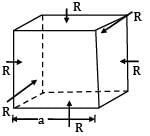
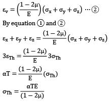
A cube having each side of length a, is constrained in all directions and is heated uniformly so that the temperature is raised by T℃ . If α is the thermal coefficient of expansion of the cube material and E the modulus of elasticity, the stress developed in the cube is

Detailed Solution for Test: Simple Stress & Strain Level - 3 - Question 6
Since the cube is restrained in all directions,

⇒ εv = εx + εy + εz ⋯ ①

Test: Simple Stress & Strain Level - 3 - Question 7

Consider the following statements: The thermal stress is induced in a component in general, when

1. a temperature gradient exists in the component

2. the component is free from any restraint

3. it is restrained to expand or contract freely

Which of the above statements are correct?

Detailed Solution for Test: Simple Stress & Strain Level - 3 - Question 7

1. If a temperature gradient exists in the component, then there will be thermal stresses generated if the component is restrained to expand or contract freely.

2. If the component is free from restraints, no stresses will be generated. However, strain will be there.

3. Thermal stresses will be induced when it is restrained to expand or contract freely.

Ex.: fixed beam with a rise in temperature.

Test: Simple Stress & Strain Level - 3 - Question 8

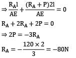
A straight bar is fixed at edges A and B. Its elastic modulus is E and cross-section is A. There is a load P = 120 N acting at C. Determine the reactions at the ends.

Detailed Solution for Test: Simple Stress & Strain Level - 3 - Question 8
The FBD can be shown as

δAC + δCB = 0

(Opposite to the direction assumed)

⇒ RB = −80 + 120 = 40N

Test: Simple Stress & Strain Level - 3 - Question 9

A rigid beam of negligible weight is supported in a horizontal position by two rods of steel and aluminum, 2m and 1m long having values of cross-sectional areas 1 cm2 and 2 cm2 and E of 200 GPa and 100 GPa respectively. A load P is applied as shown in the figure.
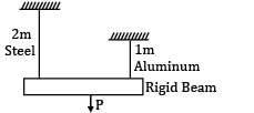
If the rigid beam is to remain horizontal then

Detailed Solution for Test: Simple Stress & Strain Level - 3 - Question 9
If the beam is to remain horizontal ⇒ δAB = δCD Let force on rod AB be P′

⇒ Force on rod CD = P − P′

⇒ 2P′ = P − P′

⇒ 3P′ = P

⇒ P′ = P/3(force on steel rod) Force on aluminum rod

⇒ Force on aluminum rod

= 2 x force on steel rod.

Test: Simple Stress & Strain Level - 3 - Question 10

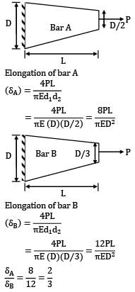
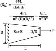
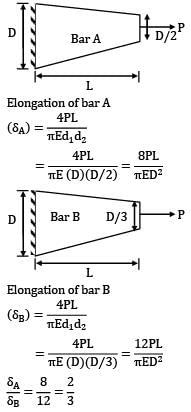
Two tapering bars of the same material are subjected to a tensile load P. The lengths of both the bars are the same. The larger diameter of each of the bars is D. The diameter of the bar A at its smaller end is D/2 and that of the bar b is D/3. What is the ratio of elongation of the bar A to that of the bar B?

Detailed Solution for Test: Simple Stress & Strain Level - 3 - Question 10

Elongation of bar A

Elongation of bar B

Test: Simple Stress & Strain Level - 3 - Question 11

For a composite bar consisting of a bar enclosed inside a tube of another material and when compressed under a load W as a whole through rigid plates at the end of the bar. The equation of compatibility is given by (Suffixes 1 and 2 refer to bar and tube respectively)

Detailed Solution for Test: Simple Stress & Strain Level - 3 - Question 11

Compatibility condition is

Elongation in bar = Elongation in tube

δ1 = δ2

Test: Simple Stress & Strain Level - 3 - Question 12

A tensile specimen with 12 mm initial diameter and 50 mm initial length is subjected to a load of 90 kN. After some time the diameter is 10 mm. Assuming it as incompressible material, Calculate the true strain along the length.

Detailed Solution for Test: Simple Stress & Strain Level - 3 - Question 12

Given,

d1 = 12 mm

l1 = 50 mm p = 90 kN

d2 = 10 mm

= 0.36

Test: Simple Stress & Strain Level - 3 - Question 13

If the rigid rod fitted snugly between the supports as shown in the figure below, is heated, the stress induced in it due to 20℃ rise in temperature will be (α = 12.5 x 10⁻⁶/℃ E = 200GPa)

Detailed Solution for Test: Simple Stress & Strain Level - 3 - Question 13
Expansion of rod due to temperature rise δ = α∆tL

= 12.5 x 10−6 x 20 x 0.5

= 1.25 x 10⁻⁴m

Force induced by the spring due to compression

F = kδ = 50 x 103 x 1.25 x 10−4 = 6.25 N

This stress is compressive for the bar,

∴ Stress = −0.07945 MPa

Test: Simple Stress & Strain Level - 3 - Question 14

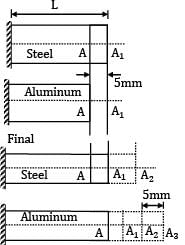
An aluminum bar of 8 m length and a steel bar of 5 mm longer in length are kept at 30℃.If the ambient temperature is raised gradually, at what temperature the aluminum bar will elongate 5 mm longer than the steel bar? (The linear expansion coefficients for steel and aluminum are 12 x 10−6/℃ and 23 x 10−6/℃ respectively)

Detailed Solution for Test: Simple Stress & Strain Level - 3 - Question 14
L = 8 m Initially,

αs = 12 x 10−6/℃

αa = 23 x 10−6/℃

t1 = 30℃

Total elongation of aluminum-total elongation of steel

= (AA3) − (A1A2)

= (AA1) + A1A2 + A2A3) − (A1A2)

= AA1 + A2A3 = 10mm

L αal∆t − Lαs∆t = 10

8 x 10³ x ∆t[23 x 10−6 − 12 x 10−6] = 10

t2 − 30° = 113.636℃

t2 = 143.636℃

Test: Simple Stress & Strain Level - 3 - Question 15

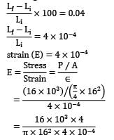
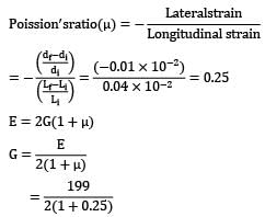
A 16 mm diameter bar elongates by 0.04% under a tensile force of 16kN. The average decrease in diameter is found to be 0.01%. Then

1. E = 210 GPa and G = 77 GPa

2. E = 199 GPa and V = 0.25

3. E = 199 GPa and V = 0.30

4. E = 199 GPa and G = 80 GPa

Which of these values are correct?

Detailed Solution for Test: Simple Stress & Strain Level - 3 - Question 15
Load (P) = 16kN

Diameter (d) = 16mm

% elongation = 0.04%

= 198.94 x 10³MPa

= 199 GPa

= 79.6

= 80 GPa

Statement 2 and 4 are correct.

Test: Simple Stress & Strain Level - 3 - Question 16

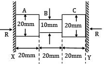
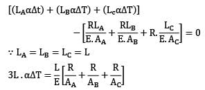
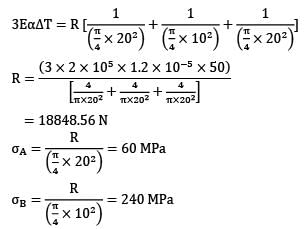
The figure shows a steel piece of diameter 20 mm at A and C, and 10 mm at B. the lengths of three sections A, B and C are each equal to 20 mm. The piece is held between two rigid surface x and Y. The coefficient of linear expansion α = 1.2 x 10⁻⁵ /℃ and Young’s Modulus E = 2 x 10⁵ MPa for steel,
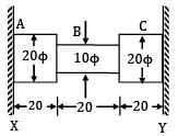
When the temperature of this piece increase by 50℃, the stresses in sections A and B are

Detailed Solution for Test: Simple Stress & Strain Level - 3 - Question 16
α = 1.2 x 10⁻⁵/℃

E = 2 x 10⁵ MPa

∆T = 50℃

Since supports are rigid

Test: Simple Stress & Strain Level - 3 - Question 17

A steel rod, 2 m long, is held between two walls and heated from 20℃ to 60℃. Young’s modulus and coefficient of linear expansion of rod material are 200 x 103 MPa and 10 x 10−6/℃ respectively. The stress induced in the rod, if walls yield by 0.2 mm, is

Detailed Solution for Test: Simple Stress & Strain Level - 3 - Question 17
L = 2 m, t1 = 20° and t2 = 60°

Temperature change (∆t) = t2 − t1 = 40℃

E = 200 x 103 MPa

α = 10 x 10−6/℃

yielding of the wall (λ) = 0.2 mm

BB1 = δth = α(∆t)L

B1 B2 = Expansion restricted by supports

λ = BB2 = yielding of support

= −100[(2000 x 10 x 10−6 x 40) − 0.2]

= −60 MPa = 60 MPa compressive

Test: Simple Stress & Strain Level - 3 - Question 18

Two steel rods of 20 mm diameter are joined end to end by means of a turn buckle as shown in figure, other end of each rod is rigidly fixed. Initially, there is no tension in each rod. Effective length of each rod is 5 m. Threads on each rod has a pitch of 2.4 mm. Calculate the increase in tension when the turn buckle is tightened by one third of revolution. E = 208 GPa. If the temperature of the rods is increased, then at what temperature, tension in each rod is reduced to half of its magnitude. αs = 11 x 10−6/℃.

Detailed Solution for Test: Simple Stress & Strain Level - 3 - Question 18
A turn buckle is a type of nut having internal threads on two ends but in opposite directions. Ends of tie rods are inserted from both the sides as shown. By rotating the turn buckle, both the tie rods are tightened.

Length of each rod = 5 m Pitch of thread = 2.4 mm

Axial movement of rods on both the sides = 2.4/ 3 = 0.8 mm

Strain in each rod = 0.8 / 5000 = 0.16 x 10⁻³

E = 208000 N/mm2

σ, stress in each rod

= 0.16 x 10−3 x 208 x 1000 = 33.28 N/mm2

Area of cross–section of each rod,

A =π / 4 x 202 = 100 π mm2

Tension in each rod, T = 100π x 33.28

= 10455 N

= 10.455 kN

Tension in rod is to be reduced to half by increasing the temperature of the bar

Test: Simple Stress & Strain Level - 3 - Question 19

A rigid bar AOB, figure, pinned at O is attached to two vertical bars of steel and brass as shown. Initially the rigid bar is horizontal and vertical rods are stress free. If the temperature of the brass bar only increased by 50℃. Then stress developed in the steel bar is __________MPa.

Neglect weight of the bars.

LB = 1, LS = 0.7 m, AS = 400 mm2,

AB = 800 mm2, αb = 22.1 x 10⁻⁶/℃,

ES = 2EB = 200 GPa.

Detailed Solution for Test: Simple Stress & Strain Level - 3 - Question 19

Free expansion of brass bar is partially prevented, because it is connected to a steel bar through a rigid bar.

Say σBT = compressive stress in brass bar due to length change

Decrease in the length of steel bar,

ls = lB

As AO = OB, (See the deformation triangles)

Say ?ST = compressive stress developed in steel bar

Compressive force in brass bar = PB

Compressive force in steel bar = PS

Moment about O

PB x 1 = PS x 1

Or

PB = PS

σBT x 800 = σST x 400 ⋯ ③

or σBT = 0.5 σST ⋯ ④

Now δlS = δlB

1.105 − 0.01 σBT = 3.5 x 10⁻³ σST

But σBT = 0.5 σST

Therefore 1.105 − 0.01 / 2x σST

= 3.5 x 10⁻³ σST 1.105

= 8.5 x 10⁻³ σST

σBT = 65 N/mm2 (compressive)

Test: Simple Stress & Strain Level - 3 - Question 20

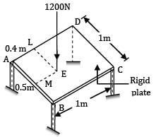
A rigid plate ABCD, 1 m2 is supported over four legs of equal lengths of same crosssection and same material. A vertical load 1200 N acts at point E such that

AM = LE = 0.5 m

AL = ME = 0.4 m

The reactions RA , RB , RC and RD are
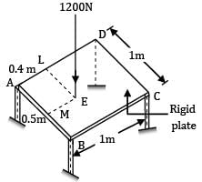
Detailed Solution for Test: Simple Stress & Strain Level - 3 - Question 20
For equilibrium RA + RB + RC + RD = 1200 N ⋯ ①

ABCD is a rigid plate, under load, its plane is changed, it is not deformed. Say under load legs deform by δA , δB , δC , δD respectively.

Diagonal AC and diagonal BD remain straight. Centre of the plate lies on both diagonals AC and BD.

δO = deflection at centre of plates

Moreover within the elastic limit, deflection is proportional to the load (or reaction) so

RA + RC = RB + RD

= 1200 / 2

= 600N ⋯ ③

Now taking moments of the forces about the edge AB

1200 x ME = I x AC + RD x 1

1200 x 0.4 = RC + RD

But RC + RD = 480

Taking moments about edge AD

1200 x 0.5 = RB x 1 + RC x 1

RB + RC = 600

RB − RC = 120

RB = 360N

RC = 240N

RA = 600 − RC

RA = 600 − 240 = 360N

RB + RD = 600

RD = 600 − RB

= 600 − 360 = 240N

Finally the reactions are RA = 360N,

RB = 360N, RC = 240N, RD = 240N

37 videos|39 docs|45 tests
Information about Test: Simple Stress & Strain Level - 3 Page
In this test you can find the Exam questions for Test: Simple Stress & Strain Level - 3 solved & explained in the simplest way possible. Besides giving Questions and answers for Test: Simple Stress & Strain Level - 3, EduRev gives you an ample number of Online tests for practice

Top Courses for Mechanical Engineering

37 videos|39 docs|45 tests
Download as PDF

Top Courses for Mechanical Engineering