Test: Single Phase FW AC-DC - 1 - Electrical Engineering (EE) MCQ
30 Questions MCQ Test - Test: Single Phase FW AC-DC - 1
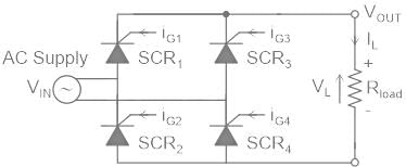
The below shown single phase controlled rectifier configuration is a
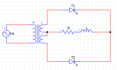
In the below shown circuit, considering the load to be purely R load, the thyristor T2 would conduct from ωt =
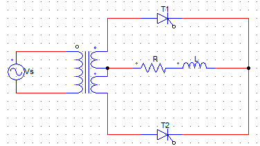
For a single pulse M-2 rectifier with RL load and firing angle α >0°, the value of the inductance L is such that the load current is continuous.
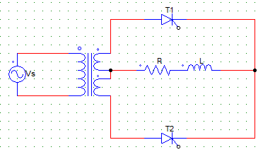
Choose the correct statement.
Choose the correct statement.
For the circuit below, the transformer ratio is 1:1 and Vs = Vm sinωt. When T1 is forward biased and is triggered at α than T2 is
The circuit turn-off time of M-2 type connection is
Find the expression for the average value of the output voltage for the below given circuit. Consider the load current to be continuous, firing angle = α, transformer ration 1:1 and Vs = Vm sinωt.
A single phase full-converter using R load is a _________ quadrant converter and that using an RL load without FD is a __________ quadrant converter
A single phase full controlled bridge converter (B-2) uses
With respect to the below given circuit, from ωt = 0 to α, ____ thyristor(s) block the forward voltage
With respect to the below given circuit, from ωt = 0 to α,
For the below given circuit, when the devices T1 and T2 are conducting from ωt = α till they are naturally commutated at π voltage across the other two pair of devices is
A single-phase full converter B-2 type connection has a RLE type of motor load connected. The minimum requirement to turn-on the device is
For the below shown circuit with continuous load current.
Each thyristor pair conducts for
For the below shown circuit has dis-continuous load current waveform.
Each thyristor pair conducts for
A single-phase full converter with B-2 type of connection has a continuous load current waveform. The thyristor pairs T3, T4 is triggered at ωt =
The PIV for each diode in a single-phase, full converter with B-2 type of controlled rectifier is
Consider supply voltage as Vs = Vm sinωt.
The below shown rectifier configuration has continues load current, find the expression for the average value of output voltage when the supply Vs = Vm sinωt is connected.
Find the expression of the rms value of output voltage for a single-phase M-2 type rectifier with RL load and continues load current. Transformer ratio is 1:1 with supply voltage Vs = Vm sinωt
A single-phase full controlled converted with RLE load will act like a line-commutated inverter when the firing angle α
In converter operation, with output voltage = Vo and RLE load.
In inverter operation, with output voltage = Vo and a RLE load connected
A motor load is connected to a single-phase full converter B-2 type controlled rectifier, the net energy is transferred from ac source to the motor (dc load) when
The below shown rectifier configuration has continues load current, find the expression of the RMS value of output voltage when the supply Vs = Vm sinωt
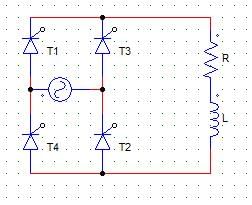
An SCR has the peak forward voltage = 1000 V. Find the maximum voltage that the SCR can handle if employed in a M-2 type full controlled converter circuit. Use factor of safety (FOS) = 2.5
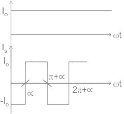
A single-phase diode bridge rectifier is used to supply a highly inductive load. If the load current is assumed to be ripple free, then the input current at the ac side of the rectifier will be


