Sinusoidal Steady-State Analysis - 1 - Free MCQ Practice Test with solutions,
MCQ Practice Test & Solutions: Test: Sinusoidal Steady-State Analysis - 1 (10 Questions)
You can prepare effectively for Electrical Engineering (EE) Topicwise Question Bank for Electrical Engineering with this dedicated MCQ Practice Test (available with solutions) on the important topic of "Test: Sinusoidal Steady-State Analysis - 1". These 10 questions have been designed by the experts with the latest curriculum of Electrical Engineering (EE) 2026, to help you master the concept.
Test Highlights:
- - Format: Multiple Choice Questions (MCQ)
- - Duration: 30 minutes
- - Number of Questions: 10
Sign up on EduRev for free to attempt this test and track your preparation progress.

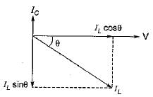
The phasor diagram shown in figure below is for a two-element series circuit having
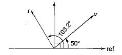
Detailed Solution: Question 1
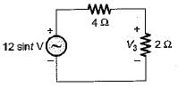
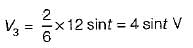
For the circuit shown below, the voltage across the 3 Ω resistor V3 is
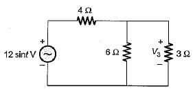
Detailed Solution: Question 2

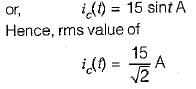
A part of a circuit shown below consists of a resistor, a capacitor and an inductor. At steady state, iR(t) = 10 sin t and vL{t) = 5 cost. The rms value of the current through the capacitor is
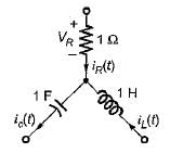
Detailed Solution: Question 3

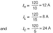
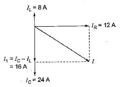
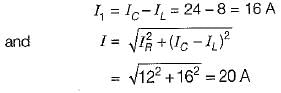
In the circuit shown below, currents I and I1 are respectively
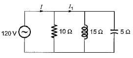
Detailed Solution: Question 4
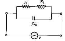
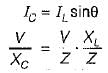
What should be the value of C for the circuit shown below such that the input power factor is unity for any frequency f of the source?
Detailed Solution: Question 5

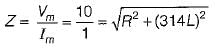
In a series R-L circuit, the current and voltages are given by
i = cos (314t-20°) , v = 10 cos ( 314 t + 10°). The values of R and L are respectively
i = cos (314t-20°) , v = 10 cos ( 314 t + 10°). The values of R and L are respectively
Detailed Solution: Question 6
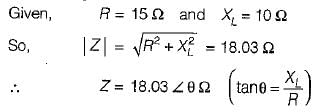
A series R-L circuit has resistance and reactance of 15 Ω and 10 Ω respectively. What should be the value of capacitor which when connected across the series combination in parallel, the system attains unity p.f.? (use f= 50 Hz)
Detailed Solution: Question 7
The input p.f. of the circuit shown below is
Detailed Solution: Question 8
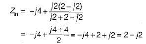
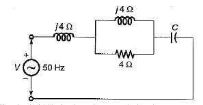
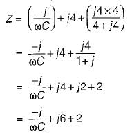
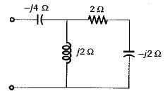
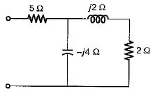
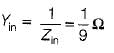
The input admittance of the circuit shown below is
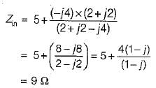
Detailed Solution: Question 9
The driving point impedance
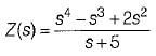
does not represents a passive one port network because
does not represents a passive one port network because