Electrical Engineering (EE) Exam  >  Electrical Engineering (EE) Tests  >  Network Theory (Electric Circuits)  >  Test: Step Response of First Order Circuits - 1 - Electrical Engineering (EE) MCQ

Test: Step Response of First Order Circuits - 1 - Electrical Engineering (EE) MCQ


Test Description

10 Questions MCQ Test Network Theory (Electric Circuits) - Test: Step Response of First Order Circuits - 1

Test: Step Response of First Order Circuits - 1 for Electrical Engineering (EE) 2024 is part of Network Theory (Electric Circuits) preparation. The Test: Step Response of First Order Circuits - 1 questions and answers have been prepared according to the Electrical Engineering (EE) exam syllabus.The Test: Step Response of First Order Circuits - 1 MCQs are made for Electrical Engineering (EE) 2024 Exam. Find important definitions, questions, notes, meanings, examples, exercises, MCQs and online tests for Test: Step Response of First Order Circuits - 1 below.
Solutions of Test: Step Response of First Order Circuits - 1 questions in English are available as part of our Network Theory (Electric Circuits) for Electrical Engineering (EE) & Test: Step Response of First Order Circuits - 1 solutions in Hindi for Network Theory (Electric Circuits) course. Download more important topics, notes, lectures and mock test series for Electrical Engineering (EE) Exam by signing up for free. Attempt Test: Step Response of First Order Circuits - 1 | 10 questions in 30 minutes | Mock test for Electrical Engineering (EE) preparation | Free important questions MCQ to study Network Theory (Electric Circuits) for Electrical Engineering (EE) Exam | Download free PDF with solutions
Test: Step Response of First Order Circuits - 1 - Question 1

Calculate the power factor of a series RL circuit having the conductance of 30 Siemens and the susceptance of 40 Siemens. 

Detailed Solution for Test: Step Response of First Order Circuits - 1 - Question 1

Concept:

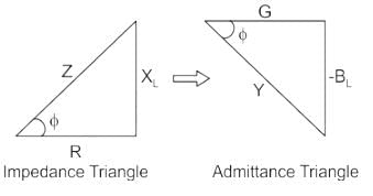
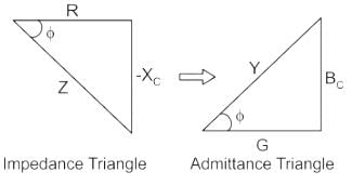
The admittance triangle is also represented similarly to the impedance triangle. As the impedance (Z) of the circuit has two rectangular components, resistance (R) and reactance (X).

Similarly, admittance (Y) also has two components, conductance (G) and susceptance (B).

Then Power factor will be:

PF = cosθ  = G/Y

Calculation:

Given;

G = 30 siemens

B = 40 Siemens

Y = √(302 + 402) = 50 Siemens

PF = cosθ = 30/50 = 0.6

Test: Step Response of First Order Circuits - 1 - Question 2

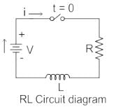
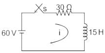
A series RL circuit (as shown in fig) has a constant voltage V = 60 V applied at t = 0. Determine the current flowing through the inductor.
Detailed Solution for Test: Step Response of First Order Circuits - 1 - Question 2

The expression of current in a series RL circuit is:

V = 60 V, R = 30, L = 15 H

Current through the inductor is,

⇒ I = 2(1 – e-2t)

1 Crore+ students have signed up on EduRev. Have you? Download the App
Test: Step Response of First Order Circuits - 1 - Question 3

Time constant in an R-L circuit is defined as the time taken by the current to become

Detailed Solution for Test: Step Response of First Order Circuits - 1 - Question 3

An L-R Series Circuit consists basically of an inductor of inductance L, connected in series with a resistor of resistance R. The resistance “R” is the resistive value of the wire turns or loops that go into making up the inductors coil.

Time constant (τ) –

The time constant is defined as the time required for the circuit to reach 63.2% of the final value (steady-state value).

*Answer can only contain numeric values
Test: Step Response of First Order Circuits - 1 - Question 4

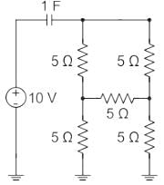
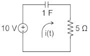
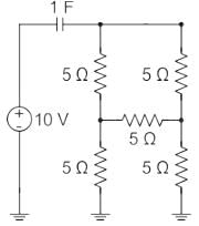
The initial charge in the 1 F capacitor present in the circuit shown is zero. The energy in joules transferred from the DC source until steady state condition is reached equals _________. (Give the answer up to one decimal place.)

Detailed Solution for Test: Step Response of First Order Circuits - 1 - Question 4

Given circuit diagram:

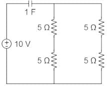
The above circuit can be redrawn as, (the above circuit forms a balanced bridge condition)

The equivalent resistance of all the 5 Ω resistors is 5 Ω 

Current in the circuit will be 

i(t) = I e-4τ

Time constant τ = RC = 5 secs

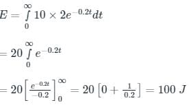
Energy transferred from the DC source,


Test: Step Response of First Order Circuits - 1 - Question 5

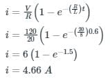
A series RL circuit having a resistance of 20 Ω and inductance of 8 H is connected to a DC voltage source of 120 V at t = 0. The current in the circuit at t = 0.6 sec is

Detailed Solution for Test: Step Response of First Order Circuits - 1 - Question 5

Concept:

The Series R-L circuit with DC source is shown below as.

Formula:

The  voltage across the resistor is 

VR = i.R

The voltage across the Inductor is 

The formula for alternating current passes through the R-L circuit is

Calculation:

Test: Step Response of First Order Circuits - 1 - Question 6

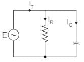
What is the phase angle between the capacitor current and the applied voltage in a parallel RC circuit?

Detailed Solution for Test: Step Response of First Order Circuits - 1 - Question 6

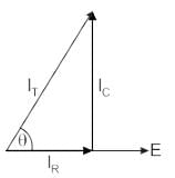
The phasor diagram is drawn as:


1) There is no phase difference between the applied voltage and the voltage across R and C in parallel.

2) The current through the resistive branch is in phase with the applied signal.

3) But the current through the capacitive branch leads its voltage Vc by 90 degrees.

.

Test: Step Response of First Order Circuits - 1 - Question 7

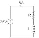
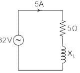
A coil takes a current of 5 A when connected to a 25 V DC supply. To obtain the same current with a 50 Hz AC supply, the voltage required was 32 V. Calculate the inductive reactance and power factor of the coil.

Detailed Solution for Test: Step Response of First Order Circuits - 1 - Question 7

Concept:-  A coil is made up of inductive reactance and Resistance.

i.e. When it is connected to the DC supply, the inductor will act as a short circuit

Hence, Resistance of the coil =  Ω

For AC supply, the inductor will offer finite reactance that will depend on the frequency of the supply.

i.e, XL = ωL

Now,

Z = V/I = 32/5 = 6.4 Ω

We know that,

Power Factor = R/Z = 5/6.4 = 0.78

And,

X2 = Z2 - R2

Hence,

Test: Step Response of First Order Circuits - 1 - Question 8

Inductive load of resistance 20 Ω and inductance 0.1 H is connected in series and switched on to an AC voltage of V = 100 sin(200 t + α). Find the angle α such that there is no transients?

Detailed Solution for Test: Step Response of First Order Circuits - 1 - Question 8

Concept:

For RL load, θ = tan-1 (ωL/R) and,

The condition for transient free response is, θ - α = 0 ⇒ θ = α

Calculation:

V = 100 sin (200t + α)

R = 20Ω, L = 0.1 H

⇒ α = 45°

Test: Step Response of First Order Circuits - 1 - Question 9

An RL circuit has a resistance of 3 ohms and a reactance of 4 ohms, the impedance of the circuit is

Detailed Solution for Test: Step Response of First Order Circuits - 1 - Question 9

Concept:

For a series RL circuit, the net impedance is given by:

Z = R + j (XL)

XL = Inductive Reactance given by:

XL = ωL

The magnitude of the impedance is:

Calculation:

With R = 3 Ω and XL = 4 Ω, we get:

|Z| = 5 Ω


Test: Step Response of First Order Circuits - 1 - Question 10

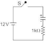
A switch is connected in between a 12 V battery and an uncharged capacitor and a 1 KΩ resistor. At the time instant when the switch is closed, the voltage across the capacitor is:

Detailed Solution for Test: Step Response of First Order Circuits - 1 - Question 10

Concept:

A capacitor doesn’t allow a sudden change in voltage across it, i.e.

Vc(0-) = Vc(0+)

Calculation:

Given circuit can be drawn as:

⇒ Vc(0-) = 0V (because the switch is open)

At t = 0+ (i.e. at the instant when the switch is closed)

Vc(0+) = 0 V

68 videos|85 docs|62 tests
Information about Test: Step Response of First Order Circuits - 1 Page
In this test you can find the Exam questions for Test: Step Response of First Order Circuits - 1 solved & explained in the simplest way possible. Besides giving Questions and answers for Test: Step Response of First Order Circuits - 1, EduRev gives you an ample number of Online tests for practice

Top Courses for Electrical Engineering (EE)

Download as PDF

Top Courses for Electrical Engineering (EE)