Electrical Engineering (EE) Exam  >  Electrical Engineering (EE) Tests  >  Network Theory (Electric Circuits)  >  Test: Step Response of Second Order Circuits - Electrical Engineering (EE) MCQ

Test: Step Response of Second Order Circuits - Electrical Engineering (EE) MCQ


Test Description

15 Questions MCQ Test Network Theory (Electric Circuits) - Test: Step Response of Second Order Circuits

Test: Step Response of Second Order Circuits for Electrical Engineering (EE) 2025 is part of Network Theory (Electric Circuits) preparation. The Test: Step Response of Second Order Circuits questions and answers have been prepared according to the Electrical Engineering (EE) exam syllabus.The Test: Step Response of Second Order Circuits MCQs are made for Electrical Engineering (EE) 2025 Exam. Find important definitions, questions, notes, meanings, examples, exercises, MCQs and online tests for Test: Step Response of Second Order Circuits below.
Solutions of Test: Step Response of Second Order Circuits questions in English are available as part of our Network Theory (Electric Circuits) for Electrical Engineering (EE) & Test: Step Response of Second Order Circuits solutions in Hindi for Network Theory (Electric Circuits) course. Download more important topics, notes, lectures and mock test series for Electrical Engineering (EE) Exam by signing up for free. Attempt Test: Step Response of Second Order Circuits | 15 questions in 45 minutes | Mock test for Electrical Engineering (EE) preparation | Free important questions MCQ to study Network Theory (Electric Circuits) for Electrical Engineering (EE) Exam | Download free PDF with solutions
*Answer can only contain numeric values
Test: Step Response of Second Order Circuits - Question 1

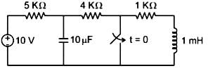
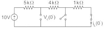
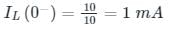
In the figure shown, the ideal switch has been open for a long time.

If it is closed at t = 0, then the magnitude of the current (in mA) through the 4kΩ resistor at t = 0+ is _______.
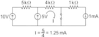

Detailed Solution for Test: Step Response of Second Order Circuits - Question 1

Concept:

Under steady-state:

  • When a capacitor, is present with a D.C supply, it behaves as an open circuit.
  • When an inductor is present with D.C supply, it behaves as a short circuit

At t = 0+ :

Inductor replace with current source IL (0+) = IL (0-)

The inductor does NOT allow the sudden change in current”

The capacitor is replaced with the voltage source

Vc (0+) = Vc (0-)

The capacitor does NOT allow the sudden change in voltage.

Calculation:

The circuit at t = 0-

Vc (0-) = 5 V

Circuit at t = 0+

I = 5/4 = 1.25mA

Test: Step Response of Second Order Circuits - Question 2

Which of the following is true for the step response of a second-order system when the damping ratio ζ is greater than 1?

Detailed Solution for Test: Step Response of Second Order Circuits - Question 2

For ζ>1\zeta > 1ζ>1, the system is overdamped, which means no oscillations occur.

Test: Step Response of Second Order Circuits - Question 3

Which of the following quantities give a measure of the transient characteristics of a control system, when subjected to unit step excitation.
1. Maximum overshoot
2. Maximum undershoot
3. Overall gain
4. Delay time
5. Rise time
6. Fall time

Detailed Solution for Test: Step Response of Second Order Circuits - Question 3

Maximum overshoot, rise time and delay time are the major factor of the transient behaviour of the system and determines the transient characteristics.

Test: Step Response of Second Order Circuits - Question 4

The time response of a second-order system with damping ratio ζ=0.6\zeta = 0.6 ζ=0.6 is shown. The peak time tp​ is the time when the system reaches its first maximum. What is the peak time in seconds?

Detailed Solution for Test: Step Response of Second Order Circuits - Question 4

Thus, substituting the values will give the required peak time in seconds.

  • The peak time (tp) for a second-order system with a damping ratio of ζ = 0.6 is determined by the following formula:

  • tp is calculated using the formula: tp = π / (ωn * √(1 - ζ²)).
  • In this formula:
    • ωn represents the natural frequency of the system.
    • ζ is the damping ratio.
  • To find the peak time, you will need to know the value of ωn.
  • Using this approach allows you to assess how quickly the system responds to changes.


Test: Step Response of Second Order Circuits - Question 5

The output in response to a unit step input for a particular continuous control system is c(t)= 1-e-t. What is the delay time Td?

Detailed Solution for Test: Step Response of Second Order Circuits - Question 5

The output is given as a function of time. The final value of the output is limn->∞c(t) = 1; .

Hence Td (at 50% of the final value) is the solution of 0.5 = 1-e-Td, and is equal to ln 2 or 0.693 sec.

Test: Step Response of Second Order Circuits - Question 6

For a second-order system with a damping ratio of 0.2, the time to reach 90% of the final value is approximately:

Detailed Solution for Test: Step Response of Second Order Circuits - Question 6

For a system with a damping ratio of 0.2, the time to reach 90% is approximated by:
t ≈ 2.2 / ωn
If ωn = 5 rad/s,
t ≈ 2.2 sec

Test: Step Response of Second Order Circuits - Question 7

The peak percentage overshoot of the closed loop system is :

Detailed Solution for Test: Step Response of Second Order Circuits - Question 7

C(s)/R(s) = 1/s2+s+1
C(s)/R(s) = w/ws+ 2Gws + w2
Compare both the equations,
w = 1 rad/sec
2Gw = 1
Mp = 16.3 %

Test: Step Response of Second Order Circuits - Question 8

What is the time required for a second-order system with damping ratio ζ = 0.5 and natural frequency ωn = 10 rad/s to reach 98% of its final value?

Detailed Solution for Test: Step Response of Second Order Circuits - Question 8

The time to reach 98% of the final value is approximately:
t = 4 / (ζ * ωn)
For ζ = 0.5 and ωn = 10,
t = 4 seconds

Test: Step Response of Second Order Circuits - Question 9

Given a second-order system with damping ratio ζ = 0.7 and natural frequency ωn = 15 rad/s, calculate the rise time for the unit step response.

Detailed Solution for Test: Step Response of Second Order Circuits - Question 9

The rise time tr for a second-order system is approximately:
tr ≈ (π - θ) / (ωn * √(1 - ζ²))
where θ = cos⁻¹(ζ).
For ζ = 0.7 and ωn = 15,
tr ≈ 0.2 sec

Test: Step Response of Second Order Circuits - Question 10

The unit step response of a second order system is = 1-e-5t-5te-5t . Consider the following statements:
1. The under damped natural frequency is 5 rad/s.
2. The damping ratio is 1.
3. The impulse response is 25te-5t.
Which of the statements given above are correct?

Detailed Solution for Test: Step Response of Second Order Circuits - Question 10

C(s) = 1/s-1/s+5-5/(s+5)^2
C(s) = 25/s(s2+10s+25)
R(s) = 1/s
G(s) = 25/(s2+10s+25 )
w= √25
w = 5 rad/sec
G = 1.

Test: Step Response of Second Order Circuits - Question 11

The unit step response of a second-order system with a damping ratio of 0.2 and natural frequency of 5 rad/s is given by:
c(t) = 1 - e^(-0.2t) * (cos(4.9t) + (0.2/0.2) * sin(4.9t))
What is the maximum overshoot in this system?

Detailed Solution for Test: Step Response of Second Order Circuits - Question 11

The maximum overshoot Mp is given by:
Mp = 100 * exp( - (ζ * π) / √(1 - ζ²))
For ζ = 0.2,
Mp ≈ 20%

Test: Step Response of Second Order Circuits - Question 12

For the system 2/s+1, the approximate time taken for a step response to reach 98% of its final value is:

Detailed Solution for Test: Step Response of Second Order Circuits - Question 12

C(s)/R(s) = 2/s+1
R(s) = 1/s (step input)
C(s) = 2/s(s+1)
c(t) = 2[1-e-t]
1.96 = 2[1-e-T]
T= 4sec.

Test: Step Response of Second Order Circuits - Question 13

For a critically damped second-order system, what is the time constant τ?

Detailed Solution for Test: Step Response of Second Order Circuits - Question 13

The time constant, τ, for a critically damped second-order system can be determined using the natural frequency, ωn. The relationship is as follows:

  • The time constant is defined as τ = 1/(2ωn).
  • This indicates that the system responds quickly without oscillating.
  • Understanding this relationship is crucial for analysing system behaviour.


Test: Step Response of Second Order Circuits - Question 14

Consider a system with transfer function G(s) = s + 6/Ks2 + s + 6. Its damping ratio will be 0.5 when the values of k is:

Detailed Solution for Test: Step Response of Second Order Circuits - Question 14

 s + 6/K[s+ s/K + 6/K]
Comparing with s+ 2Gw + w2
w = √6/K
2Gw = 1/K
2 x 0.5 x √6/K = 1/K
K = 1/6.

Test: Step Response of Second Order Circuits - Question 15

A second-order system with damping ratio ζ = 0.5 has a natural frequency of 10 rad/s. What is the overshoot for the step response of this system?

Detailed Solution for Test: Step Response of Second Order Circuits - Question 15

For a second-order system, the percentage overshoot Mp is given by the formula:
Mp = 100 * exp( - (ζ * π) / √(1 - ζ²))
Substituting ζ = 0.5 and ωn = 10 rad/s,
Mp ≈ 16.3%

68 videos|88 docs|62 tests
Information about Test: Step Response of Second Order Circuits Page
In this test you can find the Exam questions for Test: Step Response of Second Order Circuits solved & explained in the simplest way possible. Besides giving Questions and answers for Test: Step Response of Second Order Circuits, EduRev gives you an ample number of Online tests for practice
Download as PDF