Civil Engineering (CE) Exam  >  Civil Engineering (CE) Tests  >  GATE Civil Engineering (CE) 2025 Mock Test Series  >  Test: Structural Analysis- 1 - Civil Engineering (CE) MCQ

Test: Structural Analysis- 1 - Civil Engineering (CE) MCQ


Test Description

10 Questions MCQ Test GATE Civil Engineering (CE) 2025 Mock Test Series - Test: Structural Analysis- 1

Test: Structural Analysis- 1 for Civil Engineering (CE) 2024 is part of GATE Civil Engineering (CE) 2025 Mock Test Series preparation. The Test: Structural Analysis- 1 questions and answers have been prepared according to the Civil Engineering (CE) exam syllabus.The Test: Structural Analysis- 1 MCQs are made for Civil Engineering (CE) 2024 Exam. Find important definitions, questions, notes, meanings, examples, exercises, MCQs and online tests for Test: Structural Analysis- 1 below.
Solutions of Test: Structural Analysis- 1 questions in English are available as part of our GATE Civil Engineering (CE) 2025 Mock Test Series for Civil Engineering (CE) & Test: Structural Analysis- 1 solutions in Hindi for GATE Civil Engineering (CE) 2025 Mock Test Series course. Download more important topics, notes, lectures and mock test series for Civil Engineering (CE) Exam by signing up for free. Attempt Test: Structural Analysis- 1 | 10 questions in 30 minutes | Mock test for Civil Engineering (CE) preparation | Free important questions MCQ to study GATE Civil Engineering (CE) 2025 Mock Test Series for Civil Engineering (CE) Exam | Download free PDF with solutions
Test: Structural Analysis- 1 - Question 1

Match List - I (Method) with List-II (Factors) and select the correct answer using the codes given below the lists:

List - I

A. Moment distribution

B. Slope deflection

C. Kani’s method

D. Force method

List - II

1. Rotation factor

2. Flexibility

3. Hardy Cross

4. Displacements

5. Stiffness matrix

Detailed Solution for Test: Structural Analysis- 1 - Question 1

Moment Distribution Method was developed by Hardy Cross
Slope Deflection is also known as Displacement Method.
Knai’s method involves use of rotation factor.
Force Method [Force] [flexibility matrix] = Deflection  Therefore, it involves use of flexibility matrix.

Test: Structural Analysis- 1 - Question 2

In the virtual work method of plastic analysis of steel structure, the virtual quantity is

Detailed Solution for Test: Structural Analysis- 1 - Question 2

In the virtual work method of plastic analysis of steel structure, the virtual quantity is displacement.

Virtual work arises in the application of the principle of least action to the study of forces and movement of a mechanical system. The work of a force acting on a particle as it moves along a displacement will be different for different displacements. Among all the possible displacements that a particle may follow, called virtual displacements, one will minimize the action. This displacement is therefore the displacement followed by the particle according to the principle of least action. The work of a force on a particle along a virtual displacement is known as the virtual work.

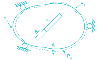
Principle of virtual work: (unit-load Method)

Developed by Bernoulli:

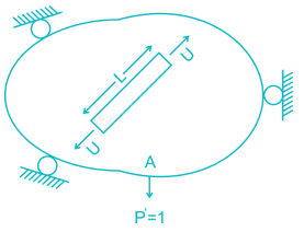
To find Δ at point A du to loads P1, P2, P3. Remove all loads, apply virtual load P’ on point A.

For simplicity P’ = 1

It creates internal load u on representative element.

Now remove this load, apply P1, P2, P3 due to which pt. A will be displaced by Δ

∴ External virtual work = 1.Δ

Internal virtual work = u.dL


P' = 1 = external virtual unit load in direction of Δ.

u = internal virtual load acting on element in direction of a dL.

Δ = external displacement caused by real loads.

dL = internal deformation caused by real loads.

1 Crore+ students have signed up on EduRev. Have you? Download the App
Test: Structural Analysis- 1 - Question 3

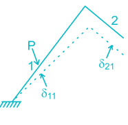
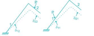
The figure below shows the displacement caused by load P at two points 1 and 2 respectively. According to Maxwell reciprocal theorem which option is CORRECT.
Detailed Solution for Test: Structural Analysis- 1 - Question 3

The Maxwell reciprocal theorem, states that the deflection at a point A in the direction of  1 due to load at point B in the direction of 2 is equal in the magnitude to the deflection of point B in the direction of 2 produced by a load applied at A in direction 1. 

Hence,

δ12 = δ21

Test: Structural Analysis- 1 - Question 4

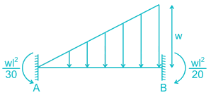
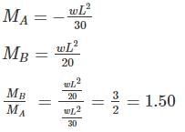
A fixed beam AB is subjected to a triangular load varying from zero at end A to ‘w’ per unit length at end B. The ratio of fixed end moment at B to A will be

Detailed Solution for Test: Structural Analysis- 1 - Question 4


The fixed end moment at end A

Test: Structural Analysis- 1 - Question 5

Find the carry over moment at support B, in the beam shown with internal hinges at C & D:-


Detailed Solution for Test: Structural Analysis- 1 - Question 5

The beam has internal hinges at C & D, so the beam can be break down as shown

In AC section moment applied = M

So the reaction will be = M/L/2 = 2/ML

The carry – over moment at B = 2M/L × L/4 = M/2

Test: Structural Analysis- 1 - Question 6

The correct order of strain energy in the beams:-

Detailed Solution for Test: Structural Analysis- 1 - Question 6

Deflection, δ = ∂U/∂F

In which beam deflection is higher, strain energy stored will be maximum.

In cantilever, the deflection will be highest.

The deflection of a simply supported beam is higher than propped cantilever as one of the support is fixed.

In a fixed beam, the deflection will be minimum.

So,

δcantilever >  δsimple-support > δpropped cantilever > δfixed

∴ Ufixed < Uproped-cantilever < Usimple-support < Ucantliver 

Test: Structural Analysis- 1 - Question 7

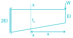
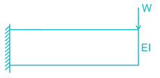
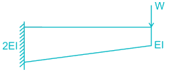
The strain energy stored (U) in the cantilever beam shown is –

Detailed Solution for Test: Structural Analysis- 1 - Question 7


BM at section X-X, Mx = W.x

Now, for


For,


∴ For 

U will be less than but greater than 

Test: Structural Analysis- 1 - Question 8

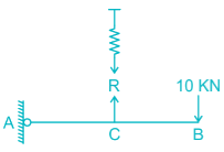
Find the vertical displacement of joint B if the spring constant k = 1 KN/mm and the rigid beam is loaded as shown below:-

Detailed Solution for Test: Structural Analysis- 1 - Question 8

The FBD of the beam will be

Taking moment about A,

R × L = 10 × 2L

R = 20 KN

So the extension of the spring will be

R = Kx

20 = 1. x

x = 20 mm

From similar triangle

δB = 20 × 2 = 40 mm

Test: Structural Analysis- 1 - Question 9

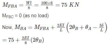
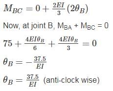
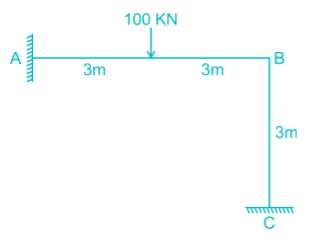
Find the rotation of joint B if the frame is loaded as shown below:
 

Detailed Solution for Test: Structural Analysis- 1 - Question 9


Test: Structural Analysis- 1 - Question 10

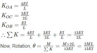
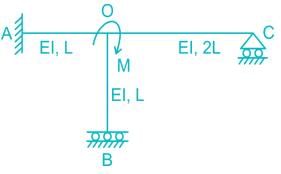
All members of the frame shown below have equal flexural rigidity EI. Calculate the rotation of joint O if moment M is applied?
Detailed Solution for Test: Structural Analysis- 1 - Question 10

Concept :-

Stiffness value, K when far end is fixed = 4EI/L

Stiffness value, K when far end is roller = 3EI/L

Stiffness value, K when far end is guided roller = EI/L

Calculation:-

For stiffness coefficient when far end is guided roller support refer
 :-

Advanced Structural Analysis, Prof. Devdas MenonDepartment of Civil Engineering, Indian Institute of Technology, Madras

Module - 5.3 ,Lecture - 29Matrix Analysis of Beams and GridsPage No. - 9


31 docs|280 tests
Information about Test: Structural Analysis- 1 Page
In this test you can find the Exam questions for Test: Structural Analysis- 1 solved & explained in the simplest way possible. Besides giving Questions and answers for Test: Structural Analysis- 1, EduRev gives you an ample number of Online tests for practice

Top Courses for Civil Engineering (CE)

Download as PDF

Top Courses for Civil Engineering (CE)