Electrical Engineering (EE) Exam  >  Electrical Engineering (EE) Tests  >  GATE Electrical Engineering (EE) Mock Test Series 2025  >  Test: Symmetrical Components - 1 - Electrical Engineering (EE) MCQ

Test: Symmetrical Components - 1 - Electrical Engineering (EE) MCQ


Test Description

12 Questions MCQ Test GATE Electrical Engineering (EE) Mock Test Series 2025 - Test: Symmetrical Components - 1

Test: Symmetrical Components - 1 for Electrical Engineering (EE) 2024 is part of GATE Electrical Engineering (EE) Mock Test Series 2025 preparation. The Test: Symmetrical Components - 1 questions and answers have been prepared according to the Electrical Engineering (EE) exam syllabus.The Test: Symmetrical Components - 1 MCQs are made for Electrical Engineering (EE) 2024 Exam. Find important definitions, questions, notes, meanings, examples, exercises, MCQs and online tests for Test: Symmetrical Components - 1 below.
Solutions of Test: Symmetrical Components - 1 questions in English are available as part of our GATE Electrical Engineering (EE) Mock Test Series 2025 for Electrical Engineering (EE) & Test: Symmetrical Components - 1 solutions in Hindi for GATE Electrical Engineering (EE) Mock Test Series 2025 course. Download more important topics, notes, lectures and mock test series for Electrical Engineering (EE) Exam by signing up for free. Attempt Test: Symmetrical Components - 1 | 12 questions in 45 minutes | Mock test for Electrical Engineering (EE) preparation | Free important questions MCQ to study GATE Electrical Engineering (EE) Mock Test Series 2025 for Electrical Engineering (EE) Exam | Download free PDF with solutions
Test: Symmetrical Components - 1 - Question 1

The line current flowing in the lines toward a balanced load connected in delta are Ia = 100∠0°, Ib = 141.4∠225°, Ic = 100∠90°. Find the symmetrical component of the line current.

Detailed Solution for Test: Symmetrical Components - 1 - Question 1

Concept:

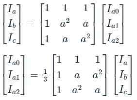
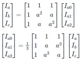
The relation between the line currents in terms of the symmetrical components of currents is given below.

Ia0 = Zero Sequence Component of Current
Ia1 = Positive Sequence Component of Current
Ia2 = Negative Sequence Component of Current
a = 1∠120°, which represents the rotation of 120° in clockwise direction.
a2 = 1∠-120° or 1∠240° in anticlockwise direction or in clockwise direction, respectively.

Calculation:
Ia = 100∠0°, Ib = 141.4∠225°, Ic = 100∠90°
Zero sequence component of current,

Positive sequence component of current,


⇒ Ia1 = 111∠15°
Negative sequence component of current,

Ia2 = 29.88 ∠ 105°

*Answer can only contain numeric values
Test: Symmetrical Components - 1 - Question 2

The series impedance matrix of a short three-phase transmission line in phase coordinates is . If the positive sequence impedance is (1 + j 10) Ω, and the zero sequence is (4 + j 31) Ω, then the imaginary part of Zm ­(in Ω) is _______ (up to 2 decimal places).


Detailed Solution for Test: Symmetrical Components - 1 - Question 2

Given that, positive sequence impedance (Z1) = (1 + j10) Ω

Zero sequence impedance (Z0) = (4 + j31) Ω

We know that, Z1 = Zs – Zm

and Z0 = Zs + 2Zm

Z1 = 1 + j10 = Zs – Zm → (1)

and Z0 = 4 + j31 = Zs + 2Zm → (2)

from equations (1) and (2)

⇒ Zm = 1 + j7

Imaginary part of Zm = 7 Ω.

1 Crore+ students have signed up on EduRev. Have you? Download the App
Test: Symmetrical Components - 1 - Question 3

In an unbalanced three phase system, phase current Ia = 1∠(-90°) pu, negative sequence current Ib2 = 4 ∠(-150°) pu, zero sequence current IC0 = 3∠ 90° pu. The magnitude of phase current Ib in pu is

Detailed Solution for Test: Symmetrical Components - 1 - Question 3

Concept:

Fortescue’s Theorem:

A unbalance set of ‘n’ phasors may be resolved into (n - 1) balance n-phase system of different phase sequence and one zero phase sequence system.

A zero-phase sequence system is one in which all phasors are of equal magnitude and angle.

Considered three phasors are represented by a, b, c in such a way that their phase sequence is (a b c).

The positive phase sequence will be (a b c) and the negative phase sequence will be (a c b).

Assumed that subscript 0, 1, 2 refer to zero sequences, positive sequence, negative sequence respectively.

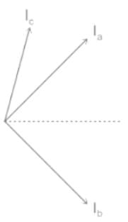
Current Ia, Ib, Ic represented an unbalance set of current phasor as shown,

Each of the original unbalance phasor is the sum of its component and it can be written as,

Ia = Ia0 + Ia1 + Ia2

Ib = Ib0 + Ib1 + Ib2

Ic = Ic0 + Ic1 + Ic2

For a balance position phase sequence (a b c) we can write the following relation,

Ia0 = Ib0 = Ic0

Ib1 = α2 Ia1

Ic1 = α Ia1

Ib2 = α Ia2

Ic2 = α2 Ia2

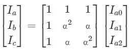
From the above equation Ia, Ib, Ic can be written in terms of phase sequence component,

Ia = Ia0 + Ia1 + Ia2

Ib = Ib0 +  α2 Ia1 + α Ia2

Ic = Ia0 + α Ia1 + α2 Ia2

The above equation can be written in form of Matrix as shown,

Calculation:
Ia = 1∠-90° P.u
Ib2 = 4∠-150° P.u
Ic0 = 3∠90° P.u
Ia = Ia1 + Ia2 + Ia0 
Ib2 = α Ia2
⇒ 4∠-150° = (1∠120°) Ia2
⇒ Ia2 = 4∠-270° 
Ia0 = Ib0 = Ic0 = 3∠90° 
Ia1 = 8∠90° 
Ib1 = α2 Ia1 = 8∠150° 
Ib = Ib0 + Ib1 + Ib2 
= 8∠150° + 4∠-150° + 3∠90° 
= 11.53∠154.4°  
Therefore the magnitude of phase current Ib in pu is 11.53∠154.4°  

Test: Symmetrical Components - 1 - Question 4

Symmetrical components are used in power system for the analysis of

Detailed Solution for Test: Symmetrical Components - 1 - Question 4

Symmetrical components:
Any unbalanced system of n phasors can be resolved into the n-system of balanced phasors. These subsystems of balanced phasors are called symmetrical components. These are used in the analysis of unbalanced three-phase faults.

Positive sequence components:
Set of three phasors equal in magnitude, displaced from each other by 120° in phase, and having the same phase sequence as the original phasors constitute positive sequence components. They are denoted by suffix 1.

Negative sequence components:
Set of three phasors equal in magnitude, displaced from each other by 120° in phase, and having phase sequence opposite to that original phasors constitute the negative sequence component. They are denoted by suffix 2.

Zero sequence components:
The set of three phasors equal in magnitude and all phases (with no mutual phase displacement) constitute zero sequence components. They are denoted by suffix 0.

Test: Symmetrical Components - 1 - Question 5

 For which of the following element the positive, negative and zero sequence impedances are equal

Detailed Solution for Test: Symmetrical Components - 1 - Question 5

Sequence Impedance:

  • The sequence impedance of the network describes the behavior of the system under asymmetrical fault conditions.

Positive Sequence Impedance

  • The impedance offered by the network to the flow of positive sequence current is called the positive sequence impedance.
  • The positive sequence means all the electrical quantities are numerically equal and displaces each other by 120º.

Negative Sequence Impedance

  • The negative sequence impedance means the impedance offered by the network to the flows of the negative sequence current.

Zero Sequence Impedance

  • The impedance offered to zero sequence current is called the zero sequence impedance.
  • Generally, resistance offered by the power system is less when compared to reactance.
  • So, the resistance of the system is neglected and reactance is considered.

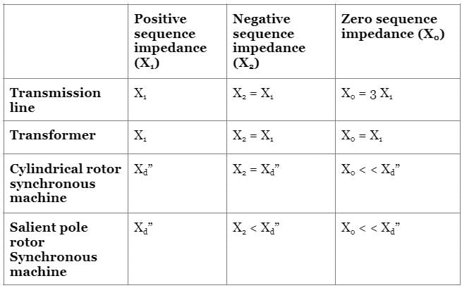
Values of sequence reactance of some equipment are as follows:

Where,
X0 is the zero sequence reactance
X1 is the positive sequence reactance
X2 is the negative sequence reactance
Xd” is the direct axis reactance

Test: Symmetrical Components - 1 - Question 6

Three synchronous generators, each of which is rated to 100 MVA, 11 KV, have an impedance per unit of 0.15. If all three generators are replaced by a single equivalent generator, what will be the effective per unit impedance of each generator?

Detailed Solution for Test: Symmetrical Components - 1 - Question 6

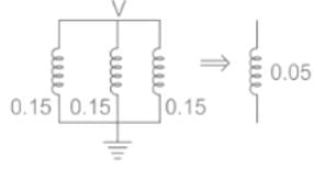
Using Thevenin's Theorem, Vth = V all the three impedances will be in parallel.

Single line diagram:

So, equivalent p.u. impedance of each generator is
Zth = Zn / 3 = 0.15 / 3 = 0.05 pu
Key Points

  • All generators are connected in parallel to increase current going to the line because all generators are at equal voltages.
  • Generators are shown with their impedances in a single line diagram.
Test: Symmetrical Components - 1 - Question 7

The line current in a three phase unbalanced load are Ia = 4 + j6, Ib = 2 - j2, Ic = -3 + j2, then zero sequence component of current will be

Detailed Solution for Test: Symmetrical Components - 1 - Question 7

Concept:
The relation between the line currents in terms of the symmetrical components of currents is given below.

Ia0 = Zero Sequence Component of Current

Ia1 = Positive Sequence Component of Current

Ia2 = Negative Sequence Component of Current

a = 1∠120°, which represents the rotation of 120° in the clockwise direction.

a2 = 1∠-120° or 1∠240° in anticlockwise direction or clockwise direction, respectively.

1 + a + a2 = 0

Calculation:

Given that

Ia = 4 + j6, Ib = 2 - j2, Ic = -3 + j2

Zero sequence component of current,


∴ I0 = 1 + j2 A

Test: Symmetrical Components - 1 - Question 8

The zero-sequence current of a generator for line to ground fault is j2.4 pu. The current through neutral during the fault is -

Detailed Solution for Test: Symmetrical Components - 1 - Question 8

Concept:
In a line to ground fault, the current through the neutral during fault is given by
If = 3Ia0

Where Ia0 is the zero sequence current of generator

Calculation:
Given that, the zero sequence current of generator for line to ground fault = j2.4 pu
The current through the neutral during the fault = 3 × j2.4 = j7.2 pu

Test: Symmetrical Components - 1 - Question 9

If the positive, negative and zero-sequence reactance of an element of a power system are 0.3, 0.3 and 0.8 p.u. respectively, then the element would be a?

Detailed Solution for Test: Symmetrical Components - 1 - Question 9

Concept:
For the transformer,
Negative sequence component = positive sequence component = zero sequence component
X0 = X1 = X2
For transmission line,
Negative sequence component = positive sequence component
Zero sequence component > positive sequence component
X0 > X1 = X2
Application:
Given that, X1 = 0.3 pu, X2 = 0.3 pu, X0 = 0.8 pu
⇒ X0 > X1 = X2
Therefore, the element is a transmission line.

Test: Symmetrical Components - 1 - Question 10

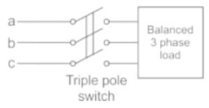
A balanced 3-phase load is supplied from a 3-phase supply. The contact in line c of the triple pole switch contactor fails to connect when switched on. If the line currents in lines a and b record 25A each, then the positive sequence component of the current is
Detailed Solution for Test: Symmetrical Components - 1 - Question 10

The contact in line C of the triple pole switch contactor fails to connect when switched on.

⇒ Ic = 0 A

And Ia + Ib = 0

⇒ Ia = -Ib

⇒ Ia = 25 ∠0°, Ib = 25 ∠-180°  
Positive sequence current,

 
= 1/3(25 ∠ 0 + 1∠120 × 25∠ −180)
= 14.4 ∠ -30° 

Test: Symmetrical Components - 1 - Question 11

Suppose IA, IB and IC are a set of unbalanced current phasors in a three-phase system. The phase-B zero-sequence current IB0 = 0.1 ∠0° p.u. If phase-A current IA = 1.1 ∠0° p.u. and phase-C current IC = (1 ∠120° + 0.1) p.u. then IB in p.u. is

Detailed Solution for Test: Symmetrical Components - 1 - Question 11

Concept:
Fortescue’s Theorem: A unbalance set of ‘n’ phasors may be resolved into (n - 1) balance n-phase system of different phase sequence and one zero phase sequence system.
A zero-phase sequence system is one in which all phasors are of equal magnitude and angle.
Considered three phasors are represented by a, b, c in such a way that their phase sequence is (a b c).
The positive phase sequence will be (a b c) and the negative phase sequence will be (a c b).
Assumed that subscript 0, 1, 2 refer to zero sequences, positive sequence, negative sequence respectively.
Current Ia, Ib, Ic represented an unbalance set of current phasor as shown,

Each of the original unbalance phasor is the sum of its component and it can be written as,

Ia = Ia0 + Ia1 + Ia2

I= Ib0 + Ib1 + Ib2

Ic = Ic0 + Ic1 + Ic2

For a balance position phase sequence (a b c) we can write the following relation,

Ia0 = Ib0 = Ic0

Ib1 = α2 Ia1

Ic1 = α Ia1

Ib2 = α Ia2

Ic2 = α2 Ia2

From the above equation Ia, Ib, Ic can be written in terms of phase sequence component,

Ia = Ia0 + Ia1 + Ia2

Ib = Ib0 +  α2 Ia1 + α Ia2

Ic = Ia0 + α Ia1 + α2 Ia2

The above equation can be written in form of Matrix as shown,

Calculation:
Given,

IB0 = 0.1 ∠0° p.u

IA0 = IB0 = IC0 = 0.1 ∠0° p.u

IA = 1.1 ∠0° p.u.

IC = (1 ∠120° + 0.1) p.u.

From the above concept,

IA = IA0 + IA1 + IA2

IA - IA0 = IA1 + IA2 = 1.1 ∠0° + 0.1 ∠0° p.u = 1 ∠0° p.u

IA1 + IA2 = 1 ∠0° p.u .... (1)

IC = IC0 + IC1 + IC2 = IA0 + α IA12 IA2

1 ∠120° + 0.1 = 0.1 ∠0° + α IA12 IA2

α IA12 IA2 = 1 ∠120° .... (2)

Adding equation (1) and (2),

(IA1 + IA2) + (α IA12 IA2) = 1 ∠0° + 1 ∠120°

IA1(α + 1) + IA22 + 1)  = 1 ∠0° + 1 ∠120° (Since, 1 + α + α2 = 0 ⇒ 1 + α = -α2)

IA1(-α2) + IA2(-α)  = 1 ∠0° + 1 ∠120°

α2 IA1 + α IA2 = 1 ∠-120° .... (3)

From above concept,

IB = IA0 + α2 IA1 + α IA2

IC = 0.1 ∠0° + 1 ∠-120°

Test: Symmetrical Components - 1 - Question 12

 For a fully transposed transmission line

Detailed Solution for Test: Symmetrical Components - 1 - Question 12

Purpose of Transposition:

  • Transmission lines are transposed to prevent interference with neighbouring telephone lines.
  • The transposition arrangement of high voltage lines helps to reduce the system power loss.
  • We have developed transposition system for Single circuit tower using same tension tower with reduced deviation angle.
  • Transposition arrangement of power line helps to reduce the effect of inductive coupling.
  • It is proved more economical Solution, in comparison of the conventional transposition system.

Important:

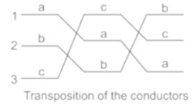
Transposition arrangement

The transposition arrangement of the conductor can simply show in the following the figure. The conductor in Position 1, Position 2 and Position 3 changes in a specific arrangement to reduce the effect of capacitance and the electrostatic unbalanced voltages.


Z1 = Z2 = ZS - Zm
Zo = ZS + 2Zm
Where,
Z1 = positive sequence impedance
Z2 = positive sequence impedance
Z= mutual impedance
Z= self impedance
Positive and negative sequence impedances are equal.

25 docs|247 tests
Information about Test: Symmetrical Components - 1 Page
In this test you can find the Exam questions for Test: Symmetrical Components - 1 solved & explained in the simplest way possible. Besides giving Questions and answers for Test: Symmetrical Components - 1, EduRev gives you an ample number of Online tests for practice

Top Courses for Electrical Engineering (EE)

Download as PDF

Top Courses for Electrical Engineering (EE)