Electrical Engineering (EE) Exam  >  Electrical Engineering (EE) Tests  >  GATE Electrical Engineering (EE) Mock Test Series 2025  >  Test: Time Domain Analysis of Control Systems- 3 - Electrical Engineering (EE) MCQ

Test: Time Domain Analysis of Control Systems- 3 - Electrical Engineering (EE) MCQ


Test Description

20 Questions MCQ Test GATE Electrical Engineering (EE) Mock Test Series 2025 - Test: Time Domain Analysis of Control Systems- 3

Test: Time Domain Analysis of Control Systems- 3 for Electrical Engineering (EE) 2024 is part of GATE Electrical Engineering (EE) Mock Test Series 2025 preparation. The Test: Time Domain Analysis of Control Systems- 3 questions and answers have been prepared according to the Electrical Engineering (EE) exam syllabus.The Test: Time Domain Analysis of Control Systems- 3 MCQs are made for Electrical Engineering (EE) 2024 Exam. Find important definitions, questions, notes, meanings, examples, exercises, MCQs and online tests for Test: Time Domain Analysis of Control Systems- 3 below.
Solutions of Test: Time Domain Analysis of Control Systems- 3 questions in English are available as part of our GATE Electrical Engineering (EE) Mock Test Series 2025 for Electrical Engineering (EE) & Test: Time Domain Analysis of Control Systems- 3 solutions in Hindi for GATE Electrical Engineering (EE) Mock Test Series 2025 course. Download more important topics, notes, lectures and mock test series for Electrical Engineering (EE) Exam by signing up for free. Attempt Test: Time Domain Analysis of Control Systems- 3 | 20 questions in 60 minutes | Mock test for Electrical Engineering (EE) preparation | Free important questions MCQ to study GATE Electrical Engineering (EE) Mock Test Series 2025 for Electrical Engineering (EE) Exam | Download free PDF with solutions
Test: Time Domain Analysis of Control Systems- 3 - Question 1

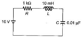
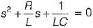
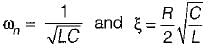
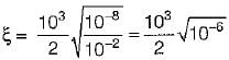
For the given series RLC circuit, damping ratio (ξ) and undamped natural frequency (ωn) are respectively given by

Detailed Solution for Test: Time Domain Analysis of Control Systems- 3 - Question 1

The characteristic equation of series RLC circuit is given by:

Comparing with s2 + 2ξωns + ωn2 = 0, we have:


Test: Time Domain Analysis of Control Systems- 3 - Question 2

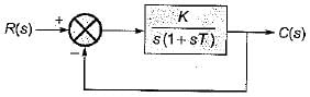
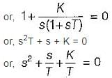
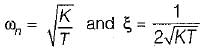
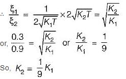
For the unity feedback control system shown below, by what factor the amplifier gain K should be multiplied so that the damping ratio is increased from 0.3 to 0.9?

Detailed Solution for Test: Time Domain Analysis of Control Systems- 3 - Question 2

Characteristic equation of given system is
1 + G(s) H(s) = 0 

Here, 

For ξ1 = 0.3, gain = K1
For ξ2 = 0.9, gain = K2

1 Crore+ students have signed up on EduRev. Have you? Download the App
Test: Time Domain Analysis of Control Systems- 3 - Question 3

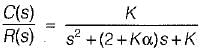
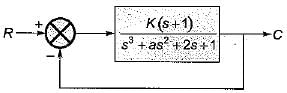
A system is shown in figure below

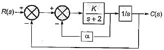
What are the values of K and α respectively so that the system has a damping ratio of 0.7 and an undamped natural frequency ωn of 4 rad/sec ?

Detailed Solution for Test: Time Domain Analysis of Control Systems- 3 - Question 3

From given block diagram, the closed loop transfer function is

Characteristic equation is,
s2 + (2 + Kα) s + K = 0
Here, ωn = -√K
and 2ξωn = (2 + kα)
Given, ωn = 4 rad/sec 
∴ K = 16
Also, ξ = 0.7
∴ 2 x 0.7 x 4 = (2 + 16α) 
or, (2 + 16α) = 5.6
or, 
α = 3.6/16 = 0.225

Test: Time Domain Analysis of Control Systems- 3 - Question 4

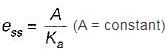
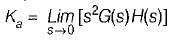
For type-2 system, the steady state error due to parabolic input is

Detailed Solution for Test: Time Domain Analysis of Control Systems- 3 - Question 4

For parabolic input, 


= Finite for type-2 system
So, ess = Some finite value

Test: Time Domain Analysis of Control Systems- 3 - Question 5

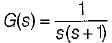
The open loop transfer function of a unity-feedback control system with unit step input is given by:

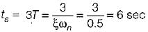
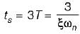
The settling time of the system for 5% tolerance band is,

Detailed Solution for Test: Time Domain Analysis of Control Systems- 3 - Question 5

Characteristic equation is: 1 + G(s) H(s) = 0 or, s2 + s + 1 = 0
Here, 

For 5% tolerance band, settling time is

Test: Time Domain Analysis of Control Systems- 3 - Question 6

The integral of a ramp function becomes

Test: Time Domain Analysis of Control Systems- 3 - Question 7

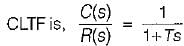
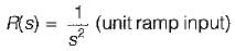
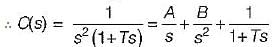
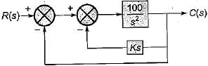
Consider a unity feedback control system as shown in figure below:

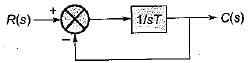
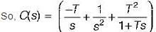
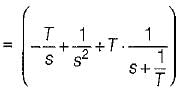
The error signal e(t) for a unit ramp input for T ≥ 0 is

Detailed Solution for Test: Time Domain Analysis of Control Systems- 3 - Question 7


Given, 


Here, A = -T, 6 = 1, C = T2


Taking inverse Laplace transform on both sides, we get:
C(t) = (-T + t + Te-t/T)
∴ Error signal,
e(t) = c(t) - r(t)
= c(t) - t = - T + Te-t/T
= T(1 - e-t/T)

Test: Time Domain Analysis of Control Systems- 3 - Question 8

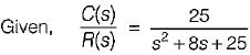
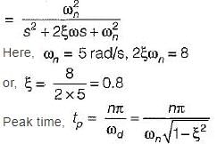
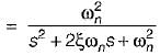
A second order system has a closed loop transfer function 

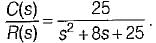
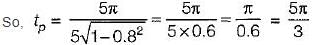
If the system is initially at rest and subjected to a unit step input at t = 0, the third peak in the response will occur at

Detailed Solution for Test: Time Domain Analysis of Control Systems- 3 - Question 8


For 3rd peak, n = 5
(3rd overshoot is the third peak)

Test: Time Domain Analysis of Control Systems- 3 - Question 9

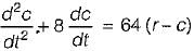
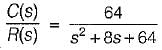
A closed servo system is represented by the differential equation

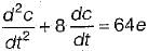
where c is the displacement of the output shaft r is the displacement of the input shaft anc e = r - c.
The damping ratio and natural frequency for this system are respectively

Detailed Solution for Test: Time Domain Analysis of Control Systems- 3 - Question 9

Given, 


or, s2C(s) + 8s C(s) = 64 [R(s) - C(s)]
or, 


Hence, ωn = 8 rad/sec
and 2ξωn = 8 or ξ = 0.5 

Test: Time Domain Analysis of Control Systems- 3 - Question 10

The poles of a closed loop control system art located at -1 ± j.
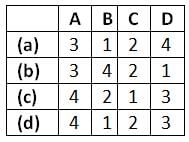
For the given system match List-I (Time domain specifications) with List - II (Values) and select the correct answer using the codes given below the lists
List - I
A. Damping ratio
B. Undamped natural frequency (rad/s)
C. Damping factor
D. Settling time (in secs)
List - II
1. 4.0
2. 1.0
3. 0.707
4. 1.414
Codes:

Detailed Solution for Test: Time Domain Analysis of Control Systems- 3 - Question 10

Given, poles are at s = -1 ± j ∴ Characteristic equation is
(s+1)2 + 1 =0
or, s2 + 2s + 2 = 0
Comparing above equation with

we have, ωn = √2 rad/sec
and 2ξωn = 2

Undamped natural frequency,
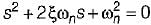
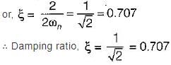
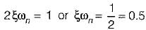
Damping factor = ξωn = 1
Settling time (For 2% tolerance band) is

Damped natural frequency is

= 1 rad/sec

Test: Time Domain Analysis of Control Systems- 3 - Question 11

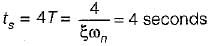
Consider the block diagram of a control system shown below.

What is the value of gain k such that the system is non oscillatory yet has the lowest possible settling time to step input?

Detailed Solution for Test: Time Domain Analysis of Control Systems- 3 - Question 11

Forward gain,

Here, ωn = 10 rad/s and 2ξωn > = 100 K
or, 

For no-oscillation and to have lowest possible settling time ξ = 1.
∴ K = 1/5 = 0.2

Test: Time Domain Analysis of Control Systems- 3 - Question 12

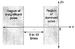
Assertion (A): The "dominant pole" concept is used to control the dynamic performance of the system, whereas the “insignificant poles” are used for the purpose of. ensuring that the controller transfer function can be realized by physical components.
Reason (R): if the magnitude of the real part of a pole is at least 5 to 10 times that of a dominant pole or a pair of complex dominant poles, the pole may be regarded as insignificant in so far as the transient response is concerned.

Detailed Solution for Test: Time Domain Analysis of Control Systems- 3 - Question 12


Both assertion and reason are true. However, the correct explanation of assertion is that the poles having real part magnitude 5 to 10 times of the magnitude of real part of dominant poles doesn't affect the transient response (dynamic performance) of the system to a great extent due to which they are termed as insignificant poies and hence are neglected for transient stability study purpose.

Test: Time Domain Analysis of Control Systems- 3 - Question 13

Assertion (A): The step-function input represents an instantaneous change in the reference input.
Reason (R): If the input is an angular position of a mechanical shaft, a step input represents the sudden rotation of the shaft.
(a) Both A and R are true and R is a correct explanation of A.
(b) Both A and R are true but R is not a correct explanation of A.
(c) A is true but R is false.
(d) A is false but R is true.

Test: Time Domain Analysis of Control Systems- 3 - Question 14

Consider the following statements related to second order control system with unit step input:
1. The right-half s-plane corresponds to negative damping.
2. Negative damping gives a response that doesn’t grows in magnitude without bound with time.
3. The imaginary axis corresponds to zero damping.
4. The maximum overshoot is often used to measure the relative stability of a control system.
5. Higher the damping in the system larger is the peak overshoot in the transient response of the system.
Which of the above statements is/are correct?

Detailed Solution for Test: Time Domain Analysis of Control Systems- 3 - Question 14

Negative damping gives a response that grows in magnitude without bound in time. Hence, statement-2 is false.
Since  therefore higher is the damping in the system, less is the peak overshoot of the system. Hence, statement-5 is not correct

Test: Time Domain Analysis of Control Systems- 3 - Question 15

Which of the following is not true regarding addition of a pole to the forward-path transfer function?

Detailed Solution for Test: Time Domain Analysis of Control Systems- 3 - Question 15

With addition of a pole to the forward-path transfer function, bandwidth will reduce.
Since therefore rise time will increase.
Since rise time  therefore stability will decrease.

Test: Time Domain Analysis of Control Systems- 3 - Question 16

For a second-order prototype system, when the undamped natural frequency is increased, the maximum overshoot of the output will

Detailed Solution for Test: Time Domain Analysis of Control Systems- 3 - Question 16

We know that, maximum overshot is

Mp is independent of wn. So M∝ ξ only.

Test: Time Domain Analysis of Control Systems- 3 - Question 17

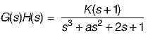
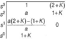
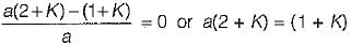
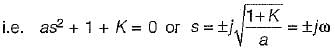
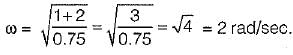
Consider a unity feedback system shown in figure below where, K > 0 and a > 0.

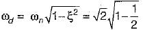
What are the values of k and a respectively so that the system oscillates at a frequency of 2 rad/sec?

Detailed Solution for Test: Time Domain Analysis of Control Systems- 3 - Question 17

Given, 

Now, 1 + G(s)H(s) = 0
or, s3 + as2 + (2 + K) s + (1 + K) = 0
Routh’s array is

For oscillation, we have:

Also, oscillating frequency will be given by roots of A2(s) = 0.

Given, 

We see that only option (d) is matching, i.e. for K = 2 and a = 0.75,

Test: Time Domain Analysis of Control Systems- 3 - Question 18

The transient response of a system is mainly due to

Test: Time Domain Analysis of Control Systems- 3 - Question 19

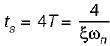
A second order system has a damping ratio ξ and undamped natural frequency of oscillation ωn respectively. The settling time at 5% of tolerance band of the system is

Detailed Solution for Test: Time Domain Analysis of Control Systems- 3 - Question 19

For 2% tolerance band,

For 5% tolerance band,

Test: Time Domain Analysis of Control Systems- 3 - Question 20

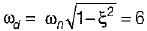
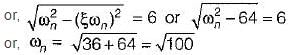
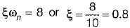
The unit impulse response of a linear time invariant second order system is
g(t) = 10e-8t sin 6t (t ≥ C)
The natural frequency and the damping ratio of the system are respectively 

Detailed Solution for Test: Time Domain Analysis of Control Systems- 3 - Question 20

Given, c(t) = g(t) = 10e-8t sin6t
Here, 

and ξωn = 8

= 10 rad/sec
So, 

25 docs|247 tests
Information about Test: Time Domain Analysis of Control Systems- 3 Page
In this test you can find the Exam questions for Test: Time Domain Analysis of Control Systems- 3 solved & explained in the simplest way possible. Besides giving Questions and answers for Test: Time Domain Analysis of Control Systems- 3, EduRev gives you an ample number of Online tests for practice

Top Courses for Electrical Engineering (EE)

Download as PDF

Top Courses for Electrical Engineering (EE)