Civil Engineering (CE) Exam  >  Civil Engineering (CE) Tests  >  RCC & Prestressed Concrete  >  Test: Working Stress Method - Civil Engineering (CE) MCQ

Test: Working Stress Method - Civil Engineering (CE) MCQ


Test Description

10 Questions MCQ Test RCC & Prestressed Concrete - Test: Working Stress Method

Test: Working Stress Method for Civil Engineering (CE) 2024 is part of RCC & Prestressed Concrete preparation. The Test: Working Stress Method questions and answers have been prepared according to the Civil Engineering (CE) exam syllabus.The Test: Working Stress Method MCQs are made for Civil Engineering (CE) 2024 Exam. Find important definitions, questions, notes, meanings, examples, exercises, MCQs and online tests for Test: Working Stress Method below.
Solutions of Test: Working Stress Method questions in English are available as part of our RCC & Prestressed Concrete for Civil Engineering (CE) & Test: Working Stress Method solutions in Hindi for RCC & Prestressed Concrete course. Download more important topics, notes, lectures and mock test series for Civil Engineering (CE) Exam by signing up for free. Attempt Test: Working Stress Method | 10 questions in 30 minutes | Mock test for Civil Engineering (CE) preparation | Free important questions MCQ to study RCC & Prestressed Concrete for Civil Engineering (CE) Exam | Download free PDF with solutions
Test: Working Stress Method - Question 1

If the permissible stress in steel in tension is 140 N / mm2, then the depth of neutral axis for a single reinforced rectangular balanced section will be 

Detailed Solution for Test: Working Stress Method - Question 1

A balanced section is one in which the area of tension steel is such that the failure of both concrete and steel occurs simultaneously.
For WSM method:
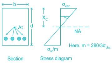
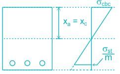
The critical depth of the neutral axis is given by –

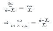
From stress distribution diagram,

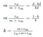
Where, Xc = kd (k = Neutral axis depth factor for balanced section)

Put the value of modular ratio, 

Thus the neutral axis factor for the balanced section depends only on σst and is independent of σcbc.
Calculation:
σst = 140 N / mm2
Neutral axis depth factor for balanced section

Hence, the depth of neutral axis for a single reinforced rectangular balanced section is 0.40d.

Test: Working Stress Method - Question 2

Which method assumes that the structural material behaves in a linearly elastic manner?

Detailed Solution for Test: Working Stress Method - Question 2

The design methods of reinforced cement concrete structures are as follows:

  • Working stress method
    • This method is based upon linear elastic theory or depends on the classical elastic theory.
    • This method ensured adequate safety by suitably restricting the stress in the materials induced by the expected working leads on the structures.
    • The basic assumption of linear elastic behavior is considered justifiable since the specified permissible stresses are kept well below the ultimate strength of the material.
    • The ratio of the yield stress of the steel reinforcement or the concrete cube strength to the corresponding permissible or working stress value is usually called a factor of safety.
  • Ultimate load method:
    • This method is based on the ultimate strength of reinforced concrete at ultimate load is obtained by enhancing the service load by some factor called load factor for giving a desired margin of safety. Hence the method is also referred to as the load factor method or the ultimate strength method.
    • In the ULM, the stress condition at the state of in pending collapse of the structure is analyzed, thus using, the non-linear stress-strain curves of concrete and steel.
    • The safety measure in the design is obtained by the use of the proper load factor.
  • Limit state method:
    • Limit states are the acceptable limits for the safety and serviceability requirements of the structure before failure occurs.
    • The design of structures by this method will thus ensure that they will not reach limit states and will not become unfit for the use for which they are intended.
    • It is worth mentioning that structures will not just fail or collapse by violating (exceeding) the limit states. Failure, therefore, implies that clearly defined limit states of structural usefulness have been exceeded.
    • Limit states are two types
      • Limit state of collapse
      • Limit state of serviceability

Kani’s method:
It is the method of structural analysis and its displacement method.

1 Crore+ students have signed up on EduRev. Have you? Download the App
Test: Working Stress Method - Question 3

The following should be arranged in ascending order based on their safety factor in the working stress method: (i) Connections, (ii) Short column, (iii) Long column, (iv) Tension members

Detailed Solution for Test: Working Stress Method - Question 3

Working stress method:

  • Working stress method is used for the design of Reinforced concrete, Steel, and Timber Structures. 
  • The main assumption in the WSM is that the behavior of structural material is restricted within the linear-elastic region and the safety of it is ensured by restricting the stresses coming on the members by working loads.
  • It assumes that both steel and concrete are elastic and obey hook's law.
  • FOS for concrete is taken as 3 and for steel, it is 1.8


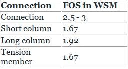
So, from the above table, the sequence of FOS will be
Short column = Tension member < Long column < Connection
Additional Information
Drawbacks of WSM:

  • It assumes the concrete is elastic which is not true.
  • It uses a factor of safety for stresses only and not for loads.
  • It gives uneconomical sections.
Test: Working Stress Method - Question 4

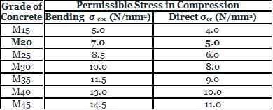
Permissible stress σcb as per IS : 456 for M20 concrete is:

Detailed Solution for Test: Working Stress Method - Question 4

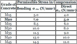
The permissible stresses under bending and direct compression as per IS 456 for different grades of concrete are given below in the tabulated form.

Test: Working Stress Method - Question 5

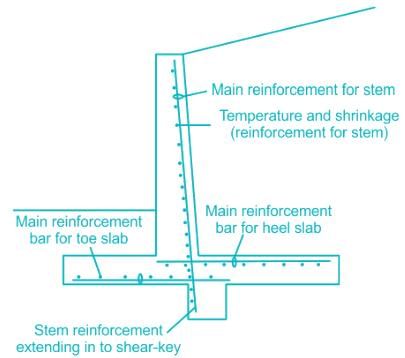
In a cantilever retaining wall, the main steel reinforcement is provided

Detailed Solution for Test: Working Stress Method - Question 5

A counterfort retaining wall is a cantilever wall with counterforts, or buttresses, attached to the inside face of the wall to further resist lateral thrust.

  • In the counterfort retaining wall, the stem and the base and the base slab are tied together by counterforts, at suitable intervals
  • Because of the provision of counterforts, the vertical stem, as well as the heel slab, acts as a continuous slab, in contrast to the cantilevers of cantilever retaining wall
  • Counterforts are firmly attached to the face slab as well as the base slab; The earth pressure acting on the face slab is transferred to the counter forts which deflect as vertical cantilevers
  • The back of the rear counter forts comes in tension and their front face is under compression
  • Hence the inclined (back) face of rear counter forts should be provided with main reinforcement and in front counterforts, the tension develops at the bottom face so it is provided with main reinforcement
  • Counterfort retaining walls are economical for height over about 6m

Test: Working Stress Method - Question 6

If the dimension of water tank is greater than 15 m in this case minimum steel requirement of steel is

Detailed Solution for Test: Working Stress Method - Question 6

(i) As per CI 8.1.1 of IS 3370:2009, The minimum reinforcement in walls. floors and roofs in each of two directions at right angles. within each surface zone shall not be less than 0.35 percent of the surface zone.
(ii) For high strength deformed bars and not less than 0.64 percent for mild steel reinforcement bars. The minimum reinforcement can be further reduced to 0.24 percent for deformed bars and 0.40 percent for plain round bars for tanks having any dimension not more than 15 m.
(iii) In wall slabs less than 200 mm in thickness, the calculated amount of reinforcement may all be placed in one face. For ground slabs less than 300 mm thick  the calculated reinforcement should be placed in one face as near as possible to the upper surface consistent with the nominal cover. Bar spacing should generally not exceed 300 mm or the thickness of the section. whichever is less.
Additional Information

  • Maximum cement content is 400 kg/m3 to take care of shrinkage effect.
  • Minimum cement content is 320 kg/m3.
  • Minimum grade of concrete is M30.
  • Maximum w/c ratio is 0.45.
  • Minimum nominal cover is 45 mm.
  • Maximum allowed crack width is 0.2 mm in LSM design.
Test: Working Stress Method - Question 7

In WSM, if the critical depth of neutral axis is equal to k × d where d is effective depth of beam, then what is the value of k for steel 500 and concrete M25?

Detailed Solution for Test: Working Stress Method - Question 7

For the given condition:

Given
Grade of Concrete = M20 , Grade of Steel = Fe500
We know
Critical depth of Neutral axis is given by:
xc = k × d

Where σst - Permissible stresses in Steel 
σcbc - Permissible stresses in concrete
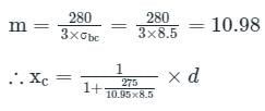
For Grade M25 → σcbc = 8.5 N/mm2
For Fe500 → σst = 0.55 × fy = 0.55 × 500 =  275 N/mm2
Equating in the formula

∴ xc = 0.2528 × d ≈ 0.253 × d
Comparing it with xc = k × d ⇒ k values come out to be 0.253
Important Points
For LSM Method,
As per IS 456:2000, cl.38.1

Test: Working Stress Method - Question 8

Steel Beam theory is the method used to analyze and in the design of a:

Detailed Solution for Test: Working Stress Method - Question 8

Steel beam theory is used to find the approximate value of the moment of resistance of a doubly reinforced beam specially when the area of compression steel is equal to or more than the area of the tensile steel.
In this theory, we assume concrete is weak in compression also then we get same amount of steel in both tension & compression, hence all the  moment will be resisted by steel only and concrete will be of no use.
In the steel beam theory :
(i) Concrete is completely neglected.
(ii) The moment of resistance is taken equal to the amount of the couple of compressive and tensile steel.
(iii) The permissible stress in compressive steel is taken as equal to the permissible stress in tensile steel.

Test: Working Stress Method - Question 9

As per IS 456 : 2000, using working stress method, the modular ratio of M25 grade of concrete for permissible compressive strength due to bending in concrete σcbc = 8.5 MPa is:

Detailed Solution for Test: Working Stress Method - Question 9

In the elastic theory for the reinforced concrete structure, concrete and reinforcing steel are converted into one material. This is done by using the modular ratio ‘m’.
Modular ratio: It is the ratio of modulus of elasticity of steel and concrete.
m = Es/Ec
However, concrete has varying moduli, as it is not a perfectly elastic material.
Therefore, its short-term modulus  is not considered and long-term modulus of elasticity is considered to take in account the effect of creep and shrinkage.
∴ The modular ratio is taken as  where σcbc is permissible compressive stress in concrete in bending.
Calculation:
Modular ratio ‘m’ (considering creep effect),

Test: Working Stress Method - Question 10

Permissible stress σcb as per IS : 456 for M20 concrete is:

Detailed Solution for Test: Working Stress Method - Question 10

The permissible stresses under bending and direct compression as per IS 456 for different grades of concrete are given below in the tabulated form.

13 videos|42 docs|34 tests
Information about Test: Working Stress Method Page
In this test you can find the Exam questions for Test: Working Stress Method solved & explained in the simplest way possible. Besides giving Questions and answers for Test: Working Stress Method, EduRev gives you an ample number of Online tests for practice

Top Courses for Civil Engineering (CE)

13 videos|42 docs|34 tests
Download as PDF

Top Courses for Civil Engineering (CE)