Electrical Engineering (EE) Exam  >  Electrical Engineering (EE) Tests  >  GATE Electrical Engineering (EE) Mock Test Series 2025  >  Test: Second Order RLC Circuits- 2 - Electrical Engineering (EE) MCQ

Test: Second Order RLC Circuits- 2 - Electrical Engineering (EE) MCQ


Test Description

15 Questions MCQ Test GATE Electrical Engineering (EE) Mock Test Series 2025 - Test: Second Order RLC Circuits- 2

Test: Second Order RLC Circuits- 2 for Electrical Engineering (EE) 2024 is part of GATE Electrical Engineering (EE) Mock Test Series 2025 preparation. The Test: Second Order RLC Circuits- 2 questions and answers have been prepared according to the Electrical Engineering (EE) exam syllabus.The Test: Second Order RLC Circuits- 2 MCQs are made for Electrical Engineering (EE) 2024 Exam. Find important definitions, questions, notes, meanings, examples, exercises, MCQs and online tests for Test: Second Order RLC Circuits- 2 below.
Solutions of Test: Second Order RLC Circuits- 2 questions in English are available as part of our GATE Electrical Engineering (EE) Mock Test Series 2025 for Electrical Engineering (EE) & Test: Second Order RLC Circuits- 2 solutions in Hindi for GATE Electrical Engineering (EE) Mock Test Series 2025 course. Download more important topics, notes, lectures and mock test series for Electrical Engineering (EE) Exam by signing up for free. Attempt Test: Second Order RLC Circuits- 2 | 15 questions in 45 minutes | Mock test for Electrical Engineering (EE) preparation | Free important questions MCQ to study GATE Electrical Engineering (EE) Mock Test Series 2025 for Electrical Engineering (EE) Exam | Download free PDF with solutions
Test: Second Order RLC Circuits- 2 - Question 1

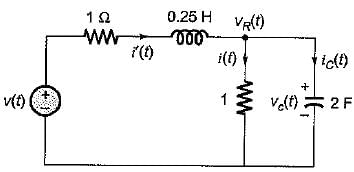
If the value of current i(t) for the circuit shown below is i(t) -20 e-2t, then the voltage source v(t) will be given by
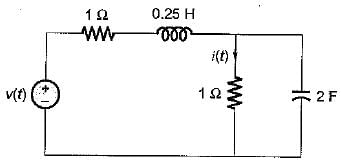
 

Detailed Solution for Test: Second Order RLC Circuits- 2 - Question 1


vR(t) = i(t) x 1 = -20 e-2t = vc(t) 

 = 80 e -2t
Now, i'(t) = i(t) + ic(t)
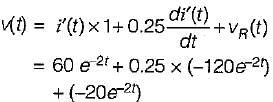
= -20 e-2t + 80 e-2t = 60 e-2t
So, 

or, 
v(t) = (60 - 30 - 20) e-2t = 10 e-2t

Test: Second Order RLC Circuits- 2 - Question 2

The circuit shown in figure is critically damped.
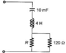
The value of R is

Detailed Solution for Test: Second Order RLC Circuits- 2 - Question 2


For an RLC series circuit to be critically damped

or, 

or, 120 R = 40 ( R + 120)
or, 3 R = R + 120 or R = 60 Ω

1 Crore+ students have signed up on EduRev. Have you? Download the App
Test: Second Order RLC Circuits- 2 - Question 3

The voltage across a passive element in an electric circuit is given by  It is given that V(0+
The value of v(t) is

Detailed Solution for Test: Second Order RLC Circuits- 2 - Question 3

Given,

Taking Laplace transform on both sides,


or, 
or, 

Using partial fraction expansion,
A = 1, B = 1,
C = - 3

So, V(t) = (t + cost - 3 sint)

Test: Second Order RLC Circuits- 2 - Question 4

A voltage is given by V(s) = 1/S(S + a). If V(∞) = 2 volts, then V(1) is 

Detailed Solution for Test: Second Order RLC Circuits- 2 - Question 4

Given, 
= 1/a = 2
or, a = 0.5
Thus, 


or v(t) = 2(1 - e - 0.5t)
Hence, v(1) = 2(1 - e-0.5)

Test: Second Order RLC Circuits- 2 - Question 5

Pole of a network is frequency at which

Test: Second Order RLC Circuits- 2 - Question 6

Transient current in an R-L-C circuit oscillatory when

Detailed Solution for Test: Second Order RLC Circuits- 2 - Question 6

Characteristic equation of series RLC circuit is

Here, 

and 

or, 

For oscillatory response,

or, 

Test: Second Order RLC Circuits- 2 - Question 7

Which of the following conditions are necessary for the validity of initial value theorem

Test: Second Order RLC Circuits- 2 - Question 8

The poles and zeros of the transfer function for the circuit shown below are located a
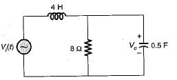
Detailed Solution for Test: Second Order RLC Circuits- 2 - Question 8

Applying KCL at the given node in s-domain, we have

or, 

or, 

Hence, there is no-zero and poles are at 4 s2 + s + 2 = 0
or, 

Test: Second Order RLC Circuits- 2 - Question 9

Assertion (A): Laplace transformation finds its application in solving the transient behaviour of the electric circuits.
Reason (R): The transient response of an electrical circuit can best be described by a linear differential equation.

Detailed Solution for Test: Second Order RLC Circuits- 2 - Question 9

Because the transient response of an electrical circuit can best be described by a differential equation hence, Laplace transformation finds its application in solving the transient behaviour of the electric circuits.

Test: Second Order RLC Circuits- 2 - Question 10

The final value of f(t) = e-t (sin 2t + cos 5t) is

Detailed Solution for Test: Second Order RLC Circuits- 2 - Question 10

f(t) = e-t sin 2t + e-2t cos 5t
∴ 

∴ Find value of f(t) is

Test: Second Order RLC Circuits- 2 - Question 11

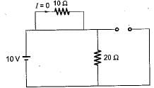
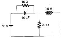
At t = 0+ with zero initial condition, the voltage across 20 Ω resistor is
Detailed Solution for Test: Second Order RLC Circuits- 2 - Question 11

At t = 0+, capacitor will act as short circuit while inductor an open circuit

∴ V20Ω = 10 volt

Test: Second Order RLC Circuits- 2 - Question 12

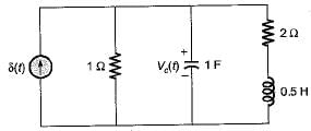
Assuming zero-initial condition vc(t) in the given circuit will be given by
Detailed Solution for Test: Second Order RLC Circuits- 2 - Question 12

Applying node analysis,

or, 

or,

Here 

∴ 
or, 

Test: Second Order RLC Circuits- 2 - Question 13

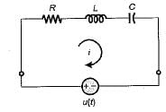
The initial and final value of current through the resistor Rina series RLC circuit with unit step input and zero initial condition are respectively 

Detailed Solution for Test: Second Order RLC Circuits- 2 - Question 13


At t = 0, inductor act as open circuit i(0+) = 0 A
At t = capacitor act as open circuit i(∞) = 0 A

Test: Second Order RLC Circuits- 2 - Question 14

The value of current through R at t = ∞ is

Detailed Solution for Test: Second Order RLC Circuits- 2 - Question 14

At t = ∞, inductor will act as short circuit anc capacitor open circuit.

Test: Second Order RLC Circuits- 2 - Question 15

Consider the following statements for a series RLC circuit excited with a voltage v(t)
1. For ξ, = 0, there is no-loss in the circuit.
2. The damping ratio of the circuit is independent of resistance R of the circuit.
3. The response of the circuit is oscillator if ξ value is more than unity.

Q. Which of the above statements is/are true?

Detailed Solution for Test: Second Order RLC Circuits- 2 - Question 15

(characteristic equation)
Therefore 

If R = 0, ξ = 0 (vice-versa) and for ξ < 1, response will be oscillatory.

25 docs|247 tests
Information about Test: Second Order RLC Circuits- 2 Page
In this test you can find the Exam questions for Test: Second Order RLC Circuits- 2 solved & explained in the simplest way possible. Besides giving Questions and answers for Test: Second Order RLC Circuits- 2, EduRev gives you an ample number of Online tests for practice

Top Courses for Electrical Engineering (EE)

Download as PDF

Top Courses for Electrical Engineering (EE)