Test: Frequency Response & Resonance- 2 - Electrical Engineering (EE) MCQ
15 Questions MCQ Test Topicwise Question Bank for Electrical Engineering - Test: Frequency Response & Resonance- 2
A series RLC circuit consist of resistance of 10 ohms, an inductance of 0.1 H and a capacitance of 0.001 μF. The frequency at resonance is
Which of the following Is not true for a series RLC resonant circuit?
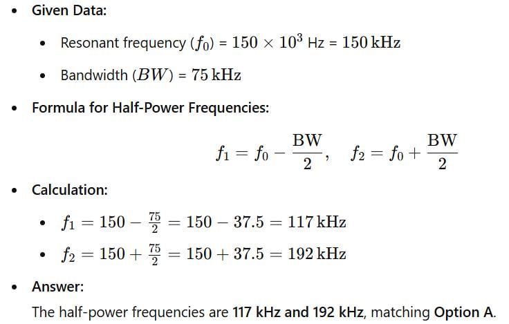
The half-power frequencies of a series resonant circuit where the resonant frequency is 150 x 103 Hz and the bandwidth is 75 kHz will be respectively given by
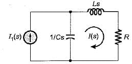
For the tank circuit shown below, the circulating current at resonance is given by

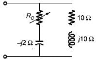
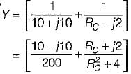
The value of RC in the circuit shown below to yield resonance will be
A resonating circuit has 10ft resistance, if the supply is 10 Ω, the power at half power frequency will be
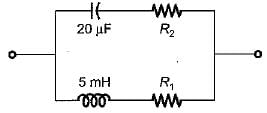
For the circuit shown below, what are the values of R1, and R2 so that the circuit will resonate at all frequencies?
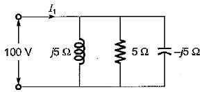
The value of current I1 in the circuit shown below is
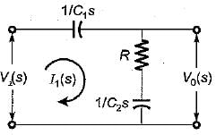
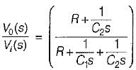
The transfer function  of the network shown below is

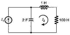
The poles and zeros of the transfer function  for the circuit shown below are located at
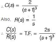
The output of a linear system for a unit step input is given by t2 e-t. The transfer function is given by
A constant voltage but variable frequency ac source feeds L and C in parallel as shown below:
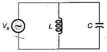
The impedance seen by source is Z
1. Z is zero when f = 0.
2. Z is zero when f = infinity.
3. Z is infinite when f = 0.
4. Z is infinite when f = infinity.
5. resonant frequency,

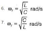
From above, the correct answer is
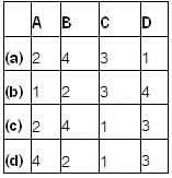
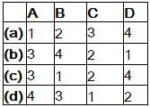
Match List- I (Types of filters) with List- II (Attenuation band) and select the correct answer using the codes given below the lists:
List -I
A. Low pass
B. High pass
C. Band pass
D. Band stop
List-II
1. 0 → f2, f1 → ∞
2. fc → ∞
3. f1 → f2
4. 0 → fc
Codes:
Match List- I (Transfer function) with List- II (Type of filter) and select the correct answer using the codes given below the lists:
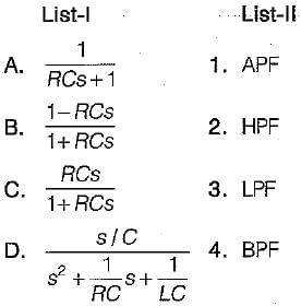
Codes:














 is for an active


