Railways Exam  >  Railways Tests  >  Test: Combinational Logic Circuits- 2 - Railways MCQ

Test: Combinational Logic Circuits- 2 - Railways MCQ


Test Description

20 Questions MCQ Test - Test: Combinational Logic Circuits- 2

Test: Combinational Logic Circuits- 2 for Railways 2024 is part of Railways preparation. The Test: Combinational Logic Circuits- 2 questions and answers have been prepared according to the Railways exam syllabus.The Test: Combinational Logic Circuits- 2 MCQs are made for Railways 2024 Exam. Find important definitions, questions, notes, meanings, examples, exercises, MCQs and online tests for Test: Combinational Logic Circuits- 2 below.
Solutions of Test: Combinational Logic Circuits- 2 questions in English are available as part of our course for Railways & Test: Combinational Logic Circuits- 2 solutions in Hindi for Railways course. Download more important topics, notes, lectures and mock test series for Railways Exam by signing up for free. Attempt Test: Combinational Logic Circuits- 2 | 20 questions in 60 minutes | Mock test for Railways preparation | Free important questions MCQ to study for Railways Exam | Download free PDF with solutions
Test: Combinational Logic Circuits- 2 - Question 1

Consider the following statements:
1. A decoder with a data input is called a demultiplexer.
2. An octal decoder with active-LOW outputs will output seven LOWs and one HIGH for each combination of inputs.
3. A hexadecimal decoder is sometimes called a 4-line-to-10-line decoder.
4. The Gray code is not a BCD-type code.
Which of the statements given above are not correct?

Test: Combinational Logic Circuits- 2 - Question 2

A multiplexer can be used as a

1 Crore+ students have signed up on EduRev. Have you? Download the App
Test: Combinational Logic Circuits- 2 - Question 3

The combinational circuit shown below has three data lines D1, D2,and D3 while one select line S.
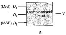
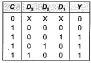
When the control line is high, the circuit is to detect when one of the data lines has ‘1’ on it. No more than one data line will ever have '1' on it. When the control line is low, the circuit will output ‘O’, regardless of what is on the data lines. The output Y of the combinational circuit will be:

Detailed Solution for Test: Combinational Logic Circuits- 2 - Question 3

The truth table for the given problem is shown below:

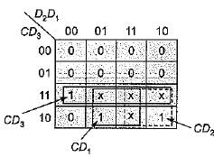
The K-map for the above truth table is shown below:

Thus output, Y = CD3 + CD2 + CD1
= C(D1 + D+ D3)

Test: Combinational Logic Circuits- 2 - Question 4

Figure below shows an automobile alarm circuit used to detect certain undesirable conditions. The three switches are used to indicate the status of the door by the driver’s seat, the ignition and the head lights, respectively.
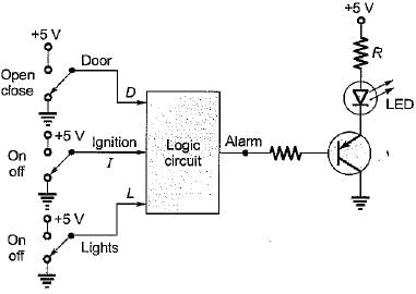
What is the output of the above logic circuit with these three switches (D, I and L) as inputs so that the alarm will be activated whenever either of the following condition exists:
The headlights are ON while the ignition is OFF.
The door is open while the ignition is ON.

Detailed Solution for Test: Combinational Logic Circuits- 2 - Question 4

Let us consider D for door, I for ignition and L for light. Then, conditions to activate the alarm are:
(i) The headlights are ON while the ignition is OFF
i.e. L = 1, I = 0 and D may be anything.
(ii) The door is open while the ignition is ON. i.e. D = 1 , I = 1, L may be anything.
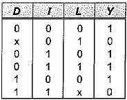
Also, alarm will sound if logic circuit output is zero.
Therefore, output (V) for above condition is zero and for rest of the condition it is 1 which is shown in following truth table.

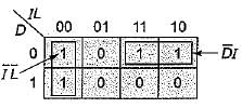
K-map for above truth table is shown below.

Thus, the output of the given logic circuit is

Test: Combinational Logic Circuits- 2 - Question 5

A logic circuit takes 4-BCD inputs {A, B, C and D) to give an output F. Output F is '1' if the input is an invalid BCD-code. The number of two input NAND gates required to implement the output Y is

Detailed Solution for Test: Combinational Logic Circuits- 2 - Question 5

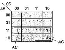
Invalid BCD inputs are from decimal 10 to 11. The K-map is shown below:

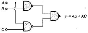
Thus, output F = AB + AC, which can be implemented using three 2-input NAND gates as shown below,.


Test: Combinational Logic Circuits- 2 - Question 6

A 1-bit full adder takes 15 ns to generate carry out bit while 35 ns for the sum bit. If we design a 4-bit adder using cascade connection of four 1-bit full-adder, then the maximum number of additions that can be performed by this 4-bit adder will be:

Detailed Solution for Test: Combinational Logic Circuits- 2 - Question 6

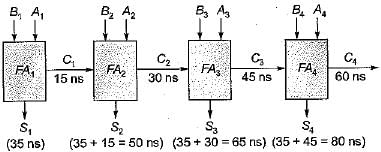
Let the binary inputs to be added be (A4 A3 A2 A1) and (B4 B3 B2 B1). A 4-bit adder using cascade connection of four 1-bit full adder is shown below. Here, C represents for carry and Sfor sum.

It is clear from above circuit that each addition requires 80 ns.
Therefore, maximum number of additions that can be performed by this 4-bit adder

= 125 x 105 additions/sec

Test: Combinational Logic Circuits- 2 - Question 7

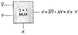
The number of two-input multiplexers required to implement an EX-NOR and a NAND gate are respectively

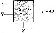
Detailed Solution for Test: Combinational Logic Circuits- 2 - Question 7

Let the two inputs variations be Xand Y.
EX-NOR gate using 2 x 1 MUX:

Here, we require two 2 x 1 MUX.
NAND g a te using 2 x 1 MUX:

Thus, we require two number of 2 x 1 MUX for NAND gate implementation.

Test: Combinational Logic Circuits- 2 - Question 8

The circuit shown below represents a

Detailed Solution for Test: Combinational Logic Circuits- 2 - Question 8

Output,

= EX-NOR gate

Test: Combinational Logic Circuits- 2 - Question 9

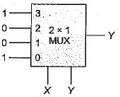
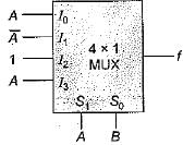
The logic expression f(A, B, C) = πM (0, 3,5) is required to be implemented using a 4 x 1 MUX as shown below.
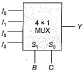
The combinations of the input to this 4 x 1 MUX circuit would be

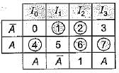
Detailed Solution for Test: Combinational Logic Circuits- 2 - Question 9

Given, logic expression is
f(A, B, C) = πM(0,3,5) = ∑m(1,2, 4, 6,7).
Here, B and C has to be control inputs while A as data inputs. We form the table as shown below:

Thus,

Test: Combinational Logic Circuits- 2 - Question 10

A full adder circuit can be implemented using:
1. One 3 x 8 decoder and two OR gates.
2. One 3 x 8 decoder, one OR gate and a NOT gate.
3. Two half adders and one OR gate.
4. Two half adders and one NOT gate.
5. Nine NAND/NOR gates.
6. 6 NAND/NOR gates.
Select the correct code from the given options.

Detailed Solution for Test: Combinational Logic Circuits- 2 - Question 10

A full adder is used to add three input bits (A, R and C) to give two outputs namely sum and carry as shown below:

For its implementation we require either of the following:

  • One 3 x 8 decoder and two OR gates.
  • Two half adders and one OR gate.
  • Nine NAND/NOR gates.
Test: Combinational Logic Circuits- 2 - Question 11

To add two 4-bit numbers using parallel adder circuit we require

Detailed Solution for Test: Combinational Logic Circuits- 2 - Question 11

To add two n-bit numbers using parallel adder circuit, we require
(n - 1) full adders and 1-half adder
or
n-full adders
or
(2n -1) half adders and (n - 1) OR gates Thus, to add two 4-bit numbers using parallel adder circuit, we require
3- full adder and 1 -half adder
or
4- full adders
or
7-half adder and 3 OR gates
Hence, option (d) is correct.

Test: Combinational Logic Circuits- 2 - Question 12

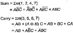
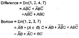
A combinational circuit has three inputs namely A, B and C (A being MSB and C being LSB).
Match List-I (Combinational Circuit outputs) with List-II (Logic expressions) and select the correct answer using the codes given below the lists:
List-I
A. Full adder carry output
B. Full subtractor borrow output
C. Sum output of full adder or difference output of full subtractor
List-II
1.
2.
3.
Codes:
     A B C
(a) 2 1 3
(b) 1 2 3
(c) 1 3 2
(d) 2 3 1

Detailed Solution for Test: Combinational Logic Circuits- 2 - Question 12


Test: Combinational Logic Circuits- 2 - Question 13

The correction to be appiied in decimal adder to the generated sum is

Detailed Solution for Test: Combinational Logic Circuits- 2 - Question 13

The correction to be applied in decimal adder to the generated sum is 00110. When the four bit sum is more than 9, then the sum is invalid, in such cases, +6 (i.e. 0110) is added to the four bit sum to skip the six invalid states, if a carry is generated when adding 6, the carry is added to the next four bit group.

Test: Combinational Logic Circuits- 2 - Question 14

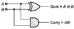
The gates required to build a half adder are:

Detailed Solution for Test: Combinational Logic Circuits- 2 - Question 14

The gates required to build a half adder are EX-OR gate and AND gate. Figure below shows the logic diagram of half adder.

Test: Combinational Logic Circuits- 2 - Question 15

The code where all successive numbers differ from their preceding number by single bit is

Detailed Solution for Test: Combinational Logic Circuits- 2 - Question 15

The code where all successive numbers differ from their preceding number by single bit is Gray code. (It is an unweighted code. The most important characteristic of this code is that only a single bit change occurs when going from one code number to next).

Test: Combinational Logic Circuits- 2 - Question 16

A device which changes from serial data to parallel data is

Detailed Solution for Test: Combinational Logic Circuits- 2 - Question 16

The device which changes from serial data to parallel data is demultiplexer because it takes in data from one line and directs it to any of its A/outputs depending on the status of the select inputs.

Test: Combinational Logic Circuits- 2 - Question 17

A device which converts BCD to Seven Segment is called

Detailed Solution for Test: Combinational Logic Circuits- 2 - Question 17

A decoder converts binary words into alphanumeric characters i.e. it converts BCD to seven segment.

Test: Combinational Logic Circuits- 2 - Question 18

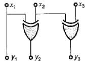
The logic circuit shown below converts a binary code x1 xx3 into

Detailed Solution for Test: Combinational Logic Circuits- 2 - Question 18

From given circuit, we have:
 y1 = x1

Thus, the given circuit will convert binary code x1, x2, xinto Gray code y1 y2 y3.

Test: Combinational Logic Circuits- 2 - Question 19

The logic circuit shown below can be minimized to

Detailed Solution for Test: Combinational Logic Circuits- 2 - Question 19

From given circuit, output is

Test: Combinational Logic Circuits- 2 - Question 20

When the set of input data to an even parity generator is 0111, the output will be

Detailed Solution for Test: Combinational Logic Circuits- 2 - Question 20

In even parity generator if number of ‘1’ is odd then output wifi be zero. Here, input 0111 has odd number of 1's, therefore output of even parity generator will be zero.

Information about Test: Combinational Logic Circuits- 2 Page
In this test you can find the Exam questions for Test: Combinational Logic Circuits- 2 solved & explained in the simplest way possible. Besides giving Questions and answers for Test: Combinational Logic Circuits- 2, EduRev gives you an ample number of Online tests for practice

Top Courses for Railways

Download as PDF

Top Courses for Railways