Electrical Engineering (EE) Exam  >  Electrical Engineering (EE) Tests  >  GATE Electrical Engineering (EE) Mock Test Series 2025  >  Test: First Order RL & RC Circuits - 1 - Electrical Engineering (EE) MCQ

Test: First Order RL & RC Circuits - 1 - Electrical Engineering (EE) MCQ


Test Description

10 Questions MCQ Test GATE Electrical Engineering (EE) Mock Test Series 2025 - Test: First Order RL & RC Circuits - 1

Test: First Order RL & RC Circuits - 1 for Electrical Engineering (EE) 2024 is part of GATE Electrical Engineering (EE) Mock Test Series 2025 preparation. The Test: First Order RL & RC Circuits - 1 questions and answers have been prepared according to the Electrical Engineering (EE) exam syllabus.The Test: First Order RL & RC Circuits - 1 MCQs are made for Electrical Engineering (EE) 2024 Exam. Find important definitions, questions, notes, meanings, examples, exercises, MCQs and online tests for Test: First Order RL & RC Circuits - 1 below.
Solutions of Test: First Order RL & RC Circuits - 1 questions in English are available as part of our GATE Electrical Engineering (EE) Mock Test Series 2025 for Electrical Engineering (EE) & Test: First Order RL & RC Circuits - 1 solutions in Hindi for GATE Electrical Engineering (EE) Mock Test Series 2025 course. Download more important topics, notes, lectures and mock test series for Electrical Engineering (EE) Exam by signing up for free. Attempt Test: First Order RL & RC Circuits - 1 | 10 questions in 30 minutes | Mock test for Electrical Engineering (EE) preparation | Free important questions MCQ to study GATE Electrical Engineering (EE) Mock Test Series 2025 for Electrical Engineering (EE) Exam | Download free PDF with solutions
Test: First Order RL & RC Circuits - 1 - Question 1

The poles of the impedance Z(s) for the network shown in figure below will be real and coincident if
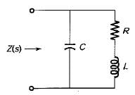
Detailed Solution for Test: First Order RL & RC Circuits - 1 - Question 1

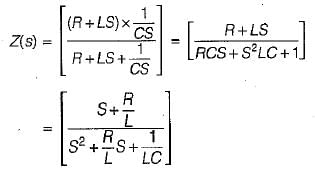
The impedance Z(s) of the given network is

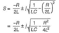
The pofes are at

Thus, the poles will be coincidence if

Test: First Order RL & RC Circuits - 1 - Question 2

In the complex frequency S= σ + jω, ω has the unit of radian/sec and σ has the unit of

1 Crore+ students have signed up on EduRev. Have you? Download the App
Test: First Order RL & RC Circuits - 1 - Question 3

A system is described by the transfer function  The value of its step response at a very large time will be close to 

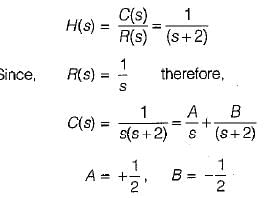
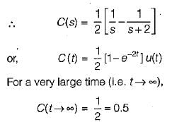
Detailed Solution for Test: First Order RL & RC Circuits - 1 - Question 3

Test: First Order RL & RC Circuits - 1 - Question 4

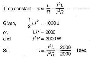
At a certain current, the energy stored in iron cored coil is 1000 J and its copper loss is 2000 W. The time constant (in second) of the coil is

Detailed Solution for Test: First Order RL & RC Circuits - 1 - Question 4

Test: First Order RL & RC Circuits - 1 - Question 5

A ramp voltage vi(t) = 100t V is applied to a differentiator circuit with R = 5 kΩ and C=4μF.The maximum output voltage is

Detailed Solution for Test: First Order RL & RC Circuits - 1 - Question 5

Maximum output voltage of RC differentiator  circuit  =

Test: First Order RL & RC Circuits - 1 - Question 6

The Laplace transform of the waveform below is 
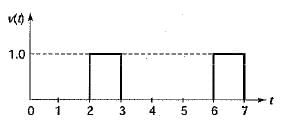
Detailed Solution for Test: First Order RL & RC Circuits - 1 - Question 6

The given waveform can be expressed as

v(t) = u ( t - 2) - u ( t - 3) + u ( t - 6) - u ( t - 7) 

Taking Laplace transform,

Test: First Order RL & RC Circuits - 1 - Question 7

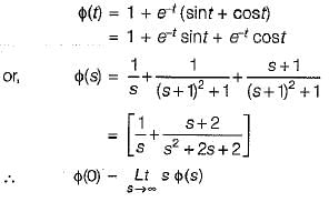
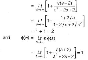
The initial and final values of  are given by 

Detailed Solution for Test: First Order RL & RC Circuits - 1 - Question 7

Test: First Order RL & RC Circuits - 1 - Question 8

The Laplace transform of the ramp function shown below is 
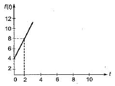
Detailed Solution for Test: First Order RL & RC Circuits - 1 - Question 8

The equation of the given ramp function is

Test: First Order RL & RC Circuits - 1 - Question 9

The poles and zeros of the transfer function   for the circuit shown below are located at
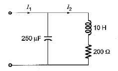
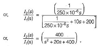
Detailed Solution for Test: First Order RL & RC Circuits - 1 - Question 9

The given circuit can be redrawn as shown below.

Hence, poles are at: 

Test: First Order RL & RC Circuits - 1 - Question 10

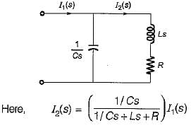
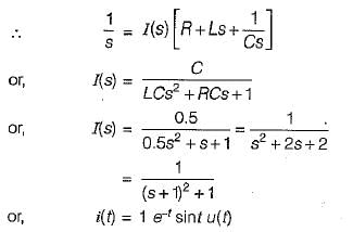
A capacitor of 0.5 F is initially charged to 1 volt and is subjected to discharge at t = 0 across a LR series circuit where 1 = 1 H; R = 2 Ω. The current i(t) for t> 0 is
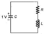
Detailed Solution for Test: First Order RL & RC Circuits - 1 - Question 10

In Laplace domain, the given circuit can be drawn as shown below.

25 docs|247 tests
Information about Test: First Order RL & RC Circuits - 1 Page
In this test you can find the Exam questions for Test: First Order RL & RC Circuits - 1 solved & explained in the simplest way possible. Besides giving Questions and answers for Test: First Order RL & RC Circuits - 1, EduRev gives you an ample number of Online tests for practice

Top Courses for Electrical Engineering (EE)

Download as PDF

Top Courses for Electrical Engineering (EE)