Electrical Engineering (EE) Exam  >  Electrical Engineering (EE) Tests  >  Topicwise Question Bank for Electrical Engineering  >  Test: Sinusoidal Steady-State Analysis- 2 - Electrical Engineering (EE) MCQ

Test: Sinusoidal Steady-State Analysis- 2 - Electrical Engineering (EE) MCQ


Test Description

10 Questions MCQ Test Topicwise Question Bank for Electrical Engineering - Test: Sinusoidal Steady-State Analysis- 2

Test: Sinusoidal Steady-State Analysis- 2 for Electrical Engineering (EE) 2024 is part of Topicwise Question Bank for Electrical Engineering preparation. The Test: Sinusoidal Steady-State Analysis- 2 questions and answers have been prepared according to the Electrical Engineering (EE) exam syllabus.The Test: Sinusoidal Steady-State Analysis- 2 MCQs are made for Electrical Engineering (EE) 2024 Exam. Find important definitions, questions, notes, meanings, examples, exercises, MCQs and online tests for Test: Sinusoidal Steady-State Analysis- 2 below.
Solutions of Test: Sinusoidal Steady-State Analysis- 2 questions in English are available as part of our Topicwise Question Bank for Electrical Engineering for Electrical Engineering (EE) & Test: Sinusoidal Steady-State Analysis- 2 solutions in Hindi for Topicwise Question Bank for Electrical Engineering course. Download more important topics, notes, lectures and mock test series for Electrical Engineering (EE) Exam by signing up for free. Attempt Test: Sinusoidal Steady-State Analysis- 2 | 10 questions in 30 minutes | Mock test for Electrical Engineering (EE) preparation | Free important questions MCQ to study Topicwise Question Bank for Electrical Engineering for Electrical Engineering (EE) Exam | Download free PDF with solutions
Test: Sinusoidal Steady-State Analysis- 2 - Question 1

The driving point admittance of the network shown below is
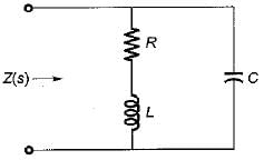
Detailed Solution for Test: Sinusoidal Steady-State Analysis- 2 - Question 1


∴ 

Test: Sinusoidal Steady-State Analysis- 2 - Question 2

Figure shown below represents a d.c. 10 V voltage source as well as a 10 V a.c. 50 Hz voltage source while Z1 and Z2 are two unknown impedances. When Z1 is connected across 10V d.c. source, it draws a current of 10 A while it draws a current of 8 A if connected across 10V a.c. source.
Now, when Z2 is connected across 10 V d.c. source, it does not draw any current while it draws a current of 5 A if connected across 10 V a.c. source.
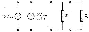
Q. What are the elements in Z1 and Z2?

Detailed Solution for Test: Sinusoidal Steady-State Analysis- 2 - Question 2

When Z1 is connected across d.c. source, it draws 10 A current.

Again, when Z1 is connected across a.c. source, it draws 8 A.

Thus,


Thus, Z1 = (1 + j0.75) Ω
Now, when Z2 is connected across 10 V d.c. source, it doesn’t draw any current. Hence, Z2 must be a capacitor which wilt act as open circuit for d.c. source.
Also, Z2 draws 5 A when connected to 10 V a.c. source.

or, 

Thus, Z2 = -j2 Ω

1 Crore+ students have signed up on EduRev. Have you? Download the App
Test: Sinusoidal Steady-State Analysis- 2 - Question 3

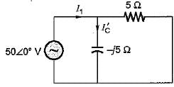
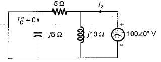
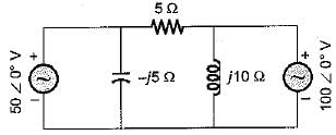
The current through the capacitor in the given circuit is
Detailed Solution for Test: Sinusoidal Steady-State Analysis- 2 - Question 3

Since two voltage sources are present, we apply. Superposition theorem to find current through the capacitor i.e. current through -j5 Ω, reactance.


Here, 

and 

So, 

Test: Sinusoidal Steady-State Analysis- 2 - Question 4

A parallel RLC circuit is said to be underdamped when

Detailed Solution for Test: Sinusoidal Steady-State Analysis- 2 - Question 4

The characteristic equation of a parallel RLC circuit is

Also, 

Thus, 

and 


for underdamped circuit, ξ < 1

Test: Sinusoidal Steady-State Analysis- 2 - Question 5

Assertion (A): A coil, when connected across 230 V dc supply, will draw more current in comparison to that when connected across 230 V ac supply.
Reason (R): The inductance of the coil opposes the flow of alternating current (not that of direct current).

Test: Sinusoidal Steady-State Analysis- 2 - Question 6

A two terminal black box contains one of the R-L-C elements. When the black box is connected to a 220 V ac supply, the current through the source is I. When a capacitance of 0.1 F is inserted in series between the source and the box, the current through the source is 2I. The element is

Detailed Solution for Test: Sinusoidal Steady-State Analysis- 2 - Question 6

As current is increased therefore, new impedance should reduce. If the unknown element will be inductive, the new impedance will be (XL- XC) Ω, so that the new value of current will increase.

Test: Sinusoidal Steady-State Analysis- 2 - Question 7

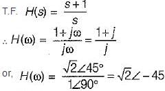
A system function has a pole at s = 0 and zero at s = -1. The constant multiplier is unity. For an excitation cost, the steady state response is given by

Detailed Solution for Test: Sinusoidal Steady-State Analysis- 2 - Question 7


Thus, 

Test: Sinusoidal Steady-State Analysis- 2 - Question 8

For the a.c. circuit given below, what is the value of I?
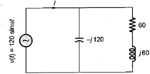
Detailed Solution for Test: Sinusoidal Steady-State Analysis- 2 - Question 8


So, 


Test: Sinusoidal Steady-State Analysis- 2 - Question 9

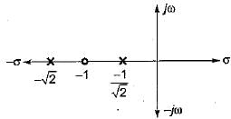
Consider the following pole-zero diagram of a system, 


What will be the magnitude of the voltage phasor for i(t) = sint?

Detailed Solution for Test: Sinusoidal Steady-State Analysis- 2 - Question 9

From the pole-zero plot,


(Since sint = i(t); ω = 1 rad/s)

so, 

Test: Sinusoidal Steady-State Analysis- 2 - Question 10

A coil takes a current of 1∠60° A (lag) from a 100 V, 50 Hz supply. The resistance of the coil is

Detailed Solution for Test: Sinusoidal Steady-State Analysis- 2 - Question 10


Also, 

or, cos 60° = R/100
or, R = 100 cos 60°

212 tests
Information about Test: Sinusoidal Steady-State Analysis- 2 Page
In this test you can find the Exam questions for Test: Sinusoidal Steady-State Analysis- 2 solved & explained in the simplest way possible. Besides giving Questions and answers for Test: Sinusoidal Steady-State Analysis- 2, EduRev gives you an ample number of Online tests for practice

Top Courses for Electrical Engineering (EE)

Download as PDF

Top Courses for Electrical Engineering (EE)