Electrical Engineering (EE) Exam  >  Electrical Engineering (EE) Tests  >  Topicwise Question Bank for Electrical Engineering  >  Test: Circuit Theorems- 3 - Electrical Engineering (EE) MCQ

Test: Circuit Theorems- 3 - Electrical Engineering (EE) MCQ


Test Description

20 Questions MCQ Test Topicwise Question Bank for Electrical Engineering - Test: Circuit Theorems- 3

Test: Circuit Theorems- 3 for Electrical Engineering (EE) 2024 is part of Topicwise Question Bank for Electrical Engineering preparation. The Test: Circuit Theorems- 3 questions and answers have been prepared according to the Electrical Engineering (EE) exam syllabus.The Test: Circuit Theorems- 3 MCQs are made for Electrical Engineering (EE) 2024 Exam. Find important definitions, questions, notes, meanings, examples, exercises, MCQs and online tests for Test: Circuit Theorems- 3 below.
Solutions of Test: Circuit Theorems- 3 questions in English are available as part of our Topicwise Question Bank for Electrical Engineering for Electrical Engineering (EE) & Test: Circuit Theorems- 3 solutions in Hindi for Topicwise Question Bank for Electrical Engineering course. Download more important topics, notes, lectures and mock test series for Electrical Engineering (EE) Exam by signing up for free. Attempt Test: Circuit Theorems- 3 | 20 questions in 60 minutes | Mock test for Electrical Engineering (EE) preparation | Free important questions MCQ to study Topicwise Question Bank for Electrical Engineering for Electrical Engineering (EE) Exam | Download free PDF with solutions
Test: Circuit Theorems- 3 - Question 1

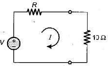
The current flowing through the resistance of 10 Ω for the circuit shown below is
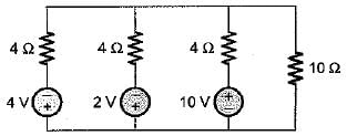
Detailed Solution for Test: Circuit Theorems- 3 - Question 1

The given circuit can be replaced by an equivalent circuit as shown below:


and 
Hence, 

Test: Circuit Theorems- 3 - Question 2

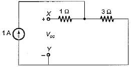
The Thevenin’s equivalent voltage source across the terminals X-Y shown below is
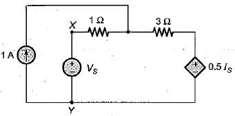
Detailed Solution for Test: Circuit Theorems- 3 - Question 2

For finding Voc' the terminal X-Y is open circuited. Thus, current through voltage source (\/s) becomes zero. i.e. Is = 0 due to which 0.5Is voltage source gets short circuited.

Thus, Voc = 3 x 1 = 3 volt

1 Crore+ students have signed up on EduRev. Have you? Download the App
Test: Circuit Theorems- 3 - Question 3

The Norton’s equivalent resistance across the diode in the given circuit is
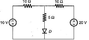
Detailed Solution for Test: Circuit Theorems- 3 - Question 3

For finding RN across diode, the independent voltage sources will be short circuited.

Hence, RN = 5 + 5 = 10 Ω

Test: Circuit Theorems- 3 - Question 4

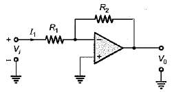
Assuming the op-amp to be ideal, the input admittance of the op-amp shown below is
Detailed Solution for Test: Circuit Theorems- 3 - Question 4

Since the op-amp is ideal, the inverting terminal will be virtually grounded.
Hence, Vi = I1 R1 
or, 
or, 

Test: Circuit Theorems- 3 - Question 5

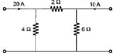
In the π-circuit shown below, the current through the 2 Ω, resistor is
Detailed Solution for Test: Circuit Theorems- 3 - Question 5

Here, we apply superposition theorem.
Taking the 20 A current source only:

Taking the 10 A current source only:

Hence, the net current through the 2 Ω resistor
= I- I2 = (6.67 - 5) A = 1.67A

Test: Circuit Theorems- 3 - Question 6

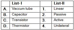
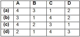
Match List-I (Elements) with List-ll (Type) and select the correct answer using the codes given below the lists:
Codes:
Test: Circuit Theorems- 3 - Question 7

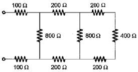
The equivalent resistance of the given circuit is

Detailed Solution for Test: Circuit Theorems- 3 - Question 7

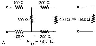
Given circuit can be reduced as shown below.


Test: Circuit Theorems- 3 - Question 8

The maximum power that a 12 V d.c. source with an interna! resistance of 2 Ω can supply toa resistive load is

Detailed Solution for Test: Circuit Theorems- 3 - Question 8

Test: Circuit Theorems- 3 - Question 9

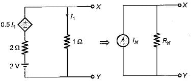
The Norton’s equivalent circuit for the circuit shown below across the terminals X-Y can be represented as a current source (IN) connected across a resistance (RN). The value of IN and RN are respectively
Detailed Solution for Test: Circuit Theorems- 3 - Question 9

Here, VX-Y = VOC = 1 x I1 = I1
Applying KVL in the loop, we have
I1 x 1 - 2 + 2 I- 0.5 I1 = 0
or, I1 - 0.8 A
Hence, VOC = 0.8 V
When the termical X-Y is short circuited then,
I1 = 0
∴ 
So,

Test: Circuit Theorems- 3 - Question 10

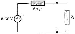
To effect maximum power transfer to the load, ZL (W) for the circuit shown below should be​

Detailed Solution for Test: Circuit Theorems- 3 - Question 10

For maximum power transfer,
ZL = ZS*
or, ZL = 6 - j4

or, ZL = 7.211 ∠-33°.69Ω

Test: Circuit Theorems- 3 - Question 11

In order to apply superposition theorem, it is necessary that the network be only

Test: Circuit Theorems- 3 - Question 12

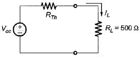
A network N is to be connected to a load of 500 ohms. If the Thevenin’s equivalent voltage and Norton’s equivalent current of N are 5 volts and 10 mA respectively, the current through the load will be

Detailed Solution for Test: Circuit Theorems- 3 - Question 12

Given, 
∴ 
= 500 Ω

Hence, the current through the load is

Test: Circuit Theorems- 3 - Question 13

If all the elements in a particular network are linear, then the superposition theorem would hold, when the excitation is

Test: Circuit Theorems- 3 - Question 14

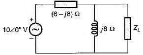
The maximum value of power transferred to the load ZL shown in figure below is
Detailed Solution for Test: Circuit Theorems- 3 - Question 14


Also, VOC across ZL is

According to maximum power transfer theorem,


Hence, 

Test: Circuit Theorems- 3 - Question 15

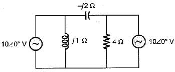
In the circuit shown below, the current through the inductive reactance is
Detailed Solution for Test: Circuit Theorems- 3 - Question 15

Let us apply superposition theorem.

Here, 
and 
∴ 
= 10 ∠- 90 ° + 0 = -j10 A

Test: Circuit Theorems- 3 - Question 16

Which of the following theorems is applicable for both linear and non-linear circuits?

Test: Circuit Theorems- 3 - Question 17

While determining RTh of a circuit
1. voltage and current sources should be left as they are.
2. all independent current and voltage sources are short-circuited.
3. all sources should be replaced by their source resistances.
4. all dependent sources remain as they are.
Q. Which of the statements is/are true in relation of RTh?

Test: Circuit Theorems- 3 - Question 18

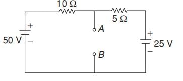
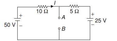
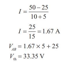
For the circuit given in figure below, the Thevenin’s voltage and resistance as seen at “AB" are respectively​

Detailed Solution for Test: Circuit Theorems- 3 - Question 18


(Using voltage divider rule)
RTh across,

Test: Circuit Theorems- 3 - Question 19

Consider the following statements about Norton’s equivalent of a circuit across a given two load terminals:
1. Norton’s equivalent resistance is the same as Thevenin’s equivalent resistance RTh.
2. Norton’s equivalent is the voltage equivalent of the network.
3. The load is connected in parallel to the Norton’s equivalent resistance.
Out of the above statements, which statements hold true?

Test: Circuit Theorems- 3 - Question 20

When the power transferred to the load is maximum, the efficiency is

212 tests
Information about Test: Circuit Theorems- 3 Page
In this test you can find the Exam questions for Test: Circuit Theorems- 3 solved & explained in the simplest way possible. Besides giving Questions and answers for Test: Circuit Theorems- 3, EduRev gives you an ample number of Online tests for practice

Top Courses for Electrical Engineering (EE)

Download as PDF

Top Courses for Electrical Engineering (EE)