Electronics and Communication Engineering (ECE) Exam  >  Electronics and Communication Engineering (ECE) Tests  >  GATE ECE (Electronics) Mock Test Series 2025  >  Test: Frequency Domain Analysis of Control Systems- 2 - Electronics and Communication Engineering (ECE) MCQ

Test: Frequency Domain Analysis of Control Systems- 2 - Electronics and Communication Engineering (ECE) MCQ


Test Description

20 Questions MCQ Test GATE ECE (Electronics) Mock Test Series 2025 - Test: Frequency Domain Analysis of Control Systems- 2

Test: Frequency Domain Analysis of Control Systems- 2 for Electronics and Communication Engineering (ECE) 2024 is part of GATE ECE (Electronics) Mock Test Series 2025 preparation. The Test: Frequency Domain Analysis of Control Systems- 2 questions and answers have been prepared according to the Electronics and Communication Engineering (ECE) exam syllabus.The Test: Frequency Domain Analysis of Control Systems- 2 MCQs are made for Electronics and Communication Engineering (ECE) 2024 Exam. Find important definitions, questions, notes, meanings, examples, exercises, MCQs and online tests for Test: Frequency Domain Analysis of Control Systems- 2 below.
Solutions of Test: Frequency Domain Analysis of Control Systems- 2 questions in English are available as part of our GATE ECE (Electronics) Mock Test Series 2025 for Electronics and Communication Engineering (ECE) & Test: Frequency Domain Analysis of Control Systems- 2 solutions in Hindi for GATE ECE (Electronics) Mock Test Series 2025 course. Download more important topics, notes, lectures and mock test series for Electronics and Communication Engineering (ECE) Exam by signing up for free. Attempt Test: Frequency Domain Analysis of Control Systems- 2 | 20 questions in 60 minutes | Mock test for Electronics and Communication Engineering (ECE) preparation | Free important questions MCQ to study GATE ECE (Electronics) Mock Test Series 2025 for Electronics and Communication Engineering (ECE) Exam | Download free PDF with solutions
Test: Frequency Domain Analysis of Control Systems- 2 - Question 1

If the bandwidth of the system is increased, then

Detailed Solution for Test: Frequency Domain Analysis of Control Systems- 2 - Question 1

We know that, 

Thus, if BW is increased, rise time will decrease and the system response will become fast. Due to faster response of system, damping ratio will decrease.

Test: Frequency Domain Analysis of Control Systems- 2 - Question 2

Polar plot of G(s) = 1/(1+Ts) is a

Detailed Solution for Test: Frequency Domain Analysis of Control Systems- 2 - Question 2

Given, G(s) = 1/(1+Ts)
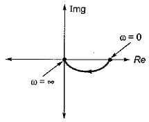
It is a type-0 and order-1 system, therefore its polar-plot will be as shown below.

Hence, the polar plot will be semicircular in shape.

1 Crore+ students have signed up on EduRev. Have you? Download the App
Test: Frequency Domain Analysis of Control Systems- 2 - Question 3

Consider the following statements related to frequency domain analysis:
1. The cut-off rate is the slope of the log magnitude curve near the cut-off frequency.
2. The bandwidth is defined as the band of frequencies lying between 3 dB points.
3. Higher the value of resonant frequency of the system, slower is the time response.
4. The magnitude of resonant peak gives the information about the relative stability of the system.
Which of these statements is/are not correct?

Detailed Solution for Test: Frequency Domain Analysis of Control Systems- 2 - Question 3

The bandwidth is defined as the band of frequencies tying between-3 dB points. Hence, statement-2 is false.
Higher the value of resonant frequency of the system, faster is the time response. Hence, statement-3 is false.

Test: Frequency Domain Analysis of Control Systems- 2 - Question 4

The inverse polar plot of the open loop transfer function, G(s) = (1+sT)/(sT) will be re presented by

Detailed Solution for Test: Frequency Domain Analysis of Control Systems- 2 - Question 4

Given, G(s) = (1+sT)/(sT)
The inverse polar plot of G(jω) is the polar plot of 1/G(jω)

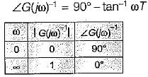
Thus, 

and

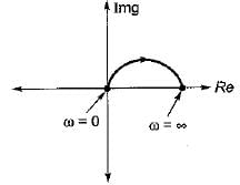
Hence, inverse polar plot will be as show below,

Test: Frequency Domain Analysis of Control Systems- 2 - Question 5

The constant M-circles corresponding to the magnitude (M) of the closed loop transfer function of a linear system for value of M less than one lie in the G-plane and to the

Test: Frequency Domain Analysis of Control Systems- 2 - Question 6

The slope of the line due to 1/(jω)factor in magnitude part of Bode plot is

Detailed Solution for Test: Frequency Domain Analysis of Control Systems- 2 - Question 6

1/(jω)2 represents type-2 factor which will have a slope of -40 db/decade.
We know that,
-20 db/decase = -6 db/octave
∴ -40 db/decase = -12 db/octave

Test: Frequency Domain Analysis of Control Systems- 2 - Question 7

The magnitude plot of the open loop transfer function G(s) of a certain system is shown in figure below.
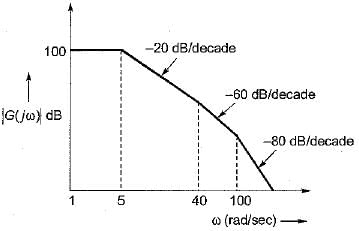
If the system is of minimum phase type, then the open-loop transfer function G(s) will be given by:

Detailed Solution for Test: Frequency Domain Analysis of Control Systems- 2 - Question 7

Since, the system is of minimum phase type, it has no poles or zeros in the right hand side of s-plane.
⇒ There will be three corner frequencies at: ω1 = 5 rad/s
∴ T1 = 1/ω1 = 0.2 sec
(one pole added at ω1 = 5 rad/s)
ω2 = 40 rad/s
∴ T2 = 1/ω2 = 0.025 sec
(two pole added at ω1 = 40 rad/s)
and ω3 = 100 rad/s
∴ T3 = 1/ω3 = 0.01 sec
(two poles added at ω3 = 100 rad/s)
So, open loop T.F. is

Now, 20 log K = 100
∴ K = 105
Thus, 

Test: Frequency Domain Analysis of Control Systems- 2 - Question 8

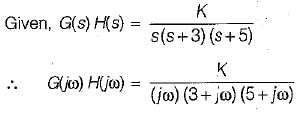
A unity feedback system has the open loop transfer function,

For the given system to be marginally stable, the value of gain cross-over frequency would be

Detailed Solution for Test: Frequency Domain Analysis of Control Systems- 2 - Question 8

For marginally stable system,
P.M = G.M = 0 and ωpc = wgc
Now, phase margin = (180° + ϕ)
Where,
 
Given, P.M = 0° (for marginally stable)
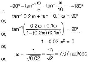
∴ 0º = 180° + ∠G(jω) H(jω)
or, ∠G(jω) H(jω) = -180°
Given, 


Thus,

Test: Frequency Domain Analysis of Control Systems- 2 - Question 9

The transfer function of a lag-lead network is given by
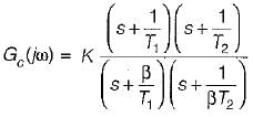
 
The phase of Gc (jω) will become zero at 

Test: Frequency Domain Analysis of Control Systems- 2 - Question 10

For the system shown below, what is the range of value of K for stability?

Detailed Solution for Test: Frequency Domain Analysis of Control Systems- 2 - Question 10


The OLTF has no-poles in RH s-plane. Thus, for stability the -1 + j0 (critical point) point should not be encircled by Nyquist plot.
For finding the point of intersection of Nyquist piot with the negative reai axis.
Img [G(jω) H(jω)] = 0
or,  -ω2 + 15 = 0
or, ω = √15 rad /sec 
Putting, ω = √15 rad/s in equation (1), we have

For system to be stable,

So, 
0 < K < 120 (for stability)

Test: Frequency Domain Analysis of Control Systems- 2 - Question 11

Match List-I (Polar plot of systems) with List-ll (Transfer functions) and select the correct answer using the codes given below the lists:
List-I
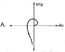
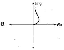
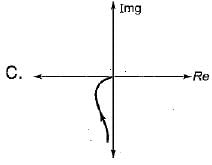
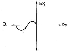
List-II
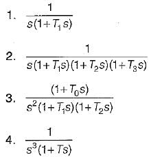
Codes:
    A B C D
(a) 3 1 2 4
(b) 2 4 1 3
(c) 2 1 4 3
(d) 1 2 3 4

Test: Frequency Domain Analysis of Control Systems- 2 - Question 12

Assertion (A): The Nyquist criterion represents a method of determining the location of the characteristic equation roots with respect to the left half and the right half of the s-plane.​
Reason (R): The Nyquist criterion does not give the exact location of the characteristic equation roots.

Test: Frequency Domain Analysis of Control Systems- 2 - Question 13

Which of the following is not true?

Detailed Solution for Test: Frequency Domain Analysis of Control Systems- 2 - Question 13

BW ∝ ωn. Hence, option (d) is not correct. For a prototype second order system,
Thus,

Test: Frequency Domain Analysis of Control Systems- 2 - Question 14

If the Nyquist plot cuts the negative real axis at a distance of 0.25, then the gain margin and phase margin of the system will be respectively

Detailed Solution for Test: Frequency Domain Analysis of Control Systems- 2 - Question 14

Here,
|X| = 0.25 (Given)

Also, ϕ = -180°
∴  P.M. = 180 + ϕ
= 180°-180° = 0°

Test: Frequency Domain Analysis of Control Systems- 2 - Question 15

Match List-I (Different values of damping ratio) with List-II (Values of resonant peaks) and select the correct answer using the codes given below the lists:
List-I               
A. ξ = 0    
B. ξ = 0.707  
C. ξ = 0.85  
D. ξ = 0.5

List-II
1. More than unity
2. Not defined
3. Unity
4. infinite
Codes:
    A B C D
(a) 1 3 2 4
(b) 4 1 2 3
(c) 4 3 2 1
(d) 1 2 3 4

Detailed Solution for Test: Frequency Domain Analysis of Control Systems- 2 - Question 15

Resonant peak is given by,

  • For ξ = 0, Mr = ∞

In frequency domainanalysis,

Thus, for ωr to be real Hence for there is no Mr or Mr is not defined.

Test: Frequency Domain Analysis of Control Systems- 2 - Question 16

Assertion (A) : Gain margin alone is adequate to indicate relative stability when system parameters other than the loop gain are subject to variation.
Reason (R) : Gain margin is the amount of gain in dB that can be added to the loop before the closed-loop system becomes unstable.

Detailed Solution for Test: Frequency Domain Analysis of Control Systems- 2 - Question 16

Gain margin alone is inadequate to indicate relative stability when system parameters other than the loop gain are subject to variation. Due to variation in some parameters, phase shift of the system can vary which may results instability. Hence, we must also consider the concept of phase margin for determining the relative stability of the system.

Test: Frequency Domain Analysis of Control Systems- 2 - Question 17

Assertion (A): Phase margin is measured at the gain crossover frequency.
Reason (R): Gain crossover frequency can be easily determined from Bode plot than from the Nyquist plot.

Test: Frequency Domain Analysis of Control Systems- 2 - Question 18

If the magnitude of closed loop transfer function of a system is given by M, then the centre and radius of M-circle will be respectively given by:

Test: Frequency Domain Analysis of Control Systems- 2 - Question 19

The open loop transfer function of a unity feedback system is given by

The value of ωpc, is

Detailed Solution for Test: Frequency Domain Analysis of Control Systems- 2 - Question 19

Given,


∴ ϕ = ∠G(jω) H(jω)
= -90° - tan-1ω - tan-1 (0.1 ω)
At  ω = ωPc, ϕ = -180°, therefore
-180° = -90 ° - tan-1ω - tan-1 (0.1 ω)
or,

= Phase crossover frequency

Test: Frequency Domain Analysis of Control Systems- 2 - Question 20

If the gain of the open-loop system is increased to four times, the gain margin of the system

Detailed Solution for Test: Frequency Domain Analysis of Control Systems- 2 - Question 20


∴ When open-loop gain becomes 4-times, GM will become one-fourth.

25 docs|263 tests
Information about Test: Frequency Domain Analysis of Control Systems- 2 Page
In this test you can find the Exam questions for Test: Frequency Domain Analysis of Control Systems- 2 solved & explained in the simplest way possible. Besides giving Questions and answers for Test: Frequency Domain Analysis of Control Systems- 2, EduRev gives you an ample number of Online tests for practice

Top Courses for Electronics and Communication Engineering (ECE)

Download as PDF

Top Courses for Electronics and Communication Engineering (ECE)