Test: Slope & Deflection Level - 2 - Mechanical Engineering MCQ
15 Questions MCQ Test Strength of Materials (SOM) - Test: Slope & Deflection Level - 2
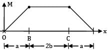
For the beam shown in the figure, the elastic curve between the supports B and C will be


The maximum deflection of a cantilever of 10.0 m span, an EI = 200.0MN/m2 subjected to a distributed load of 8.0 kN/m is
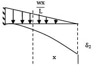
A cantilever of length (L) carries a distributed load whose intensity varies uniformly from zero at the fixed end to ‘w’ per unit length at the free end. The deflection at the free end will be
If the deflection at the free end of a uniformly loaded cantilever beam is 15 mm and the slope of the deflection curve at the free end is 0.02 radian. then the length of the beam is
A cantilever beam of uniform cross-section and length L is subjected to upward force W at mid-span and downward force P at the free end. For the deflection to be zero at the free end. W and P are related by
The slope at the free end of a cantilever of length 1 m is 1°. If the cantilever carries uniformly distributed load over the whole length then the deflection at the free end will be
A simply supported beam 'A' of length L carries a central point load W. Another beam 'B' is loaded with a uniformly distributed load such that the total load on the beam is W. The ratio of maximum deflections between the beams A and B is
A simply supported beam of span 4m subjected to a point load of 4 kN at a distance of 3m from the left support. The maximum slope occurs
If the depth of a simply supported rectangular beam subjected to concentric load at the Centre is doubled, the deflection at the Centre will be reduced to
A simply supported rectangular beam of span L and depth d carries a central load W, modulus of elasticity is E, the ratio of maximum deflection to maximum bending stress is
A cantilever of span L subjected to uniformly distributed gravity loading w/m is subjected to an upward force P at a distance L/2 from the free end. If the deflection at the free end of the beam is zero, (wL/P) is
A simply supported beam of 10m span is carrying a load of 4.8kN at mid-span. If Young's modulus of elasticity (E) is 2 x 10⁸ kN/m2 and moment of inertia (I) is 20 cm4 , then the maximum deflection will be
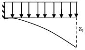
Two cantilever beams A and B are shown in the figure. The ratio of maximum deflections of beam A to the beam B is


A loaded cantilever beam is shown below. The maximum deflection in the beam is
![]()
A cantilever of length ‘L’ carries a uniformly distributed load of ‘w’ per unit of span over the outer half. The maximum deflection is
|
37 videos|41 docs|47 tests
|


