Electrical Engineering (EE) Exam  >  Electrical Engineering (EE) Tests  >  Control Systems  >  Test: Frequency Domain Analysis of Control Systems- 3 - Electrical Engineering (EE) MCQ

Test: Frequency Domain Analysis of Control Systems- 3 - Electrical Engineering (EE) MCQ


Test Description

20 Questions MCQ Test Control Systems - Test: Frequency Domain Analysis of Control Systems- 3

Test: Frequency Domain Analysis of Control Systems- 3 for Electrical Engineering (EE) 2024 is part of Control Systems preparation. The Test: Frequency Domain Analysis of Control Systems- 3 questions and answers have been prepared according to the Electrical Engineering (EE) exam syllabus.The Test: Frequency Domain Analysis of Control Systems- 3 MCQs are made for Electrical Engineering (EE) 2024 Exam. Find important definitions, questions, notes, meanings, examples, exercises, MCQs and online tests for Test: Frequency Domain Analysis of Control Systems- 3 below.
Solutions of Test: Frequency Domain Analysis of Control Systems- 3 questions in English are available as part of our Control Systems for Electrical Engineering (EE) & Test: Frequency Domain Analysis of Control Systems- 3 solutions in Hindi for Control Systems course. Download more important topics, notes, lectures and mock test series for Electrical Engineering (EE) Exam by signing up for free. Attempt Test: Frequency Domain Analysis of Control Systems- 3 | 20 questions in 60 minutes | Mock test for Electrical Engineering (EE) preparation | Free important questions MCQ to study Control Systems for Electrical Engineering (EE) Exam | Download free PDF with solutions
Test: Frequency Domain Analysis of Control Systems- 3 - Question 1

Phase crossover frequency is defined at

Test: Frequency Domain Analysis of Control Systems- 3 - Question 2

The Bode plot for a transfer function is shown below:

The steady state error corresponding to a parabolic input is

Detailed Solution for Test: Frequency Domain Analysis of Control Systems- 3 - Question 2

Initial slope of the system = 0 dB/decade
Therefore, given system is a type-0 system.
For type-0 system, for parabolic input, steady state error is infinite since,

1 Crore+ students have signed up on EduRev. Have you? Download the App
Test: Frequency Domain Analysis of Control Systems- 3 - Question 3

The frequency at which the Nyquist plot crosses the negative real axis is known as

Detailed Solution for Test: Frequency Domain Analysis of Control Systems- 3 - Question 3

At ω = ωgc, ϕ = -180°
i.e. Nyquist plot crosses the negative real axis.

Test: Frequency Domain Analysis of Control Systems- 3 - Question 4

A unity feedback system has a forward path gain of

The phase angle of the Nyquist plot for ω → ∞ is

Detailed Solution for Test: Frequency Domain Analysis of Control Systems- 3 - Question 4


At ω → ∞, ϕ = -90° - 90° - 90° = -270° = +90°

Test: Frequency Domain Analysis of Control Systems- 3 - Question 5

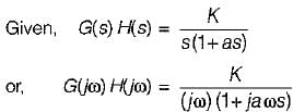
The open loop transfer function of a system is given as

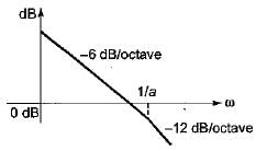
The Bode plot of this system is represented as:

Detailed Solution for Test: Frequency Domain Analysis of Control Systems- 3 - Question 5


Initial slope = -20 dB/decade
= -6 dB/octave (Since Type = 1)
Corner frequency is,
ω= (1/a) rad/sec
Initial slope = -20 dB/decade
= -6 dB/octave (Since Type = 1)
Corner frequency is,
ωc = 1/a rad/sec
It will cross 0 dB line at ω = K and K < 1/a.
So, the Bode plot will be as shown below.

Test: Frequency Domain Analysis of Control Systems- 3 - Question 6

A second order system has

It’s Mp (peak magnitude) will be approximately

Detailed Solution for Test: Frequency Domain Analysis of Control Systems- 3 - Question 6


∴ ξ = 1/√2
So, peak magnitude = 1 + e-π ≈ 1

Test: Frequency Domain Analysis of Control Systems- 3 - Question 7

The closed loop transfer function of a control system is given by 
C(s)/R(s) = 1/(1+s)
For the input r(t) = sint, the steady state value of c(t) is equal to

Detailed Solution for Test: Frequency Domain Analysis of Control Systems- 3 - Question 7

Given,
C(s)/R(s) = 1/(1+s)
Thus,

Here,
ω = 1 rad/s

and  ∠H(jω) = -tan-1ω = -tan-1(1)

∴ 

Test: Frequency Domain Analysis of Control Systems- 3 - Question 8

A system has transfer function equal to (1-s)/(1+s). Its gain at ω = 1 rad/s is

Detailed Solution for Test: Frequency Domain Analysis of Control Systems- 3 - Question 8

Given transfer function represents an all pass filter which has gain of 1 at all frequencies.

Test: Frequency Domain Analysis of Control Systems- 3 - Question 9

The gain margin of a unity negative feedback system having forward path transfer function 

Detailed Solution for Test: Frequency Domain Analysis of Control Systems- 3 - Question 9


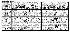
∠G(jω) H(jω) = -90° - tan-1ωT = ϕ
At ω = ωpc,
ϕ = -180º
∴ -90° - tan-1ωpc = -180° or, ωpc = ∞ rad/s

∴ 

Test: Frequency Domain Analysis of Control Systems- 3 - Question 10

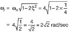
The characteristic equation of a closed loop control system is given by s2 + 4s + 16 = 0. The resonant frequency (in radian/sec) of the system is

Detailed Solution for Test: Frequency Domain Analysis of Control Systems- 3 - Question 10

Given, s2 + 4s+ 16 = 0
or 
∴ ωn = 4 rad/s
and 
∴ Resonant frequency,

Test: Frequency Domain Analysis of Control Systems- 3 - Question 11

The gain margin (in dB) of a system having the open-loop transfer function 
 is

Detailed Solution for Test: Frequency Domain Analysis of Control Systems- 3 - Question 11

Given,

∴ 

and ∠G{jω)H(jω) = -90° - tan-1 ω = ϕ
At ω = ωpc, ϕ = -180°
∴ -90° - tan-1 ωpc = -180° or ωpc = ∞
∴ 

Test: Frequency Domain Analysis of Control Systems- 3 - Question 12

The forward path transfer function of an unity feedback system is given by

What is the phase margin for this system?

Detailed Solution for Test: Frequency Domain Analysis of Control Systems- 3 - Question 12

Given,


Now,
∠G(jω) = -2tan-1ω = ϕ
At
ω = ωgc = 0 rad/s
ϕ = -2 x 0 = 0º
∴   P.M. = 180° + ϕ
= 180° + 0° = 180° = π

Test: Frequency Domain Analysis of Control Systems- 3 - Question 13

The closed loop system having the open loop transfer function,
 is

Detailed Solution for Test: Frequency Domain Analysis of Control Systems- 3 - Question 13

Given,


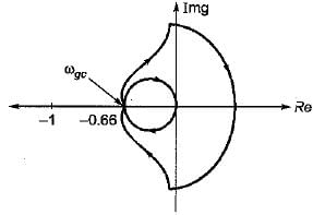
For finding ωgc, Img[G(jω)H(jω)] = 0
or, 
Now,


Thus, Nyquist plot will cut real axis at -0.66.
The given system:

of type-1 and order-3.
Therefore, Nyquist plot will be as shown below:

Now, from above Nyquist plot,
N = 0 = Number of encirclements.
Also, P = number of open loop poles in RH s-plane = 0
Now, N = P-Z
or, 0 = 0 - Z or Z = 0
Thus, no. of closed loop poles in RH s-plane = 0.
Hence, system is stable.

Test: Frequency Domain Analysis of Control Systems- 3 - Question 14

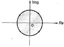
The nyquist plot for a unity feedback control system having open loop transfer function G(s) = K(1-s)/(s+1) is shown in figure below :
The system is

Detailed Solution for Test: Frequency Domain Analysis of Control Systems- 3 - Question 14

Given,
G(s)H(s) = K(1-s)/(s+1)
or,


Thus, the radius of Nyquist plot will be K.
Now, no.of open loop poles in RH s-piane = 0.
When K > 1, no. of encirclement, N = -1
When K< 1, no. of encirclement, N = 0
Thus, for K > 1, N = P - Z
or,    -1 = 0 - Z or Z = 1
∴ System is unstable.
For K < 1, N = P - Z or 0 = 0 - Z or Z = 0
∴ System is stable..

Test: Frequency Domain Analysis of Control Systems- 3 - Question 15

A unity feedback control system has a forward path transfer function of Its phase value will be zero at a frequency of ω1.
Which one of the following equation should be satisfied for it?

Detailed Solution for Test: Frequency Domain Analysis of Control Systems- 3 - Question 15

Given,


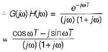
or, ∠G(jω) H(jω) = -ωT - 90° - tan-1 ω
At ω = ω1, ∠G(jω) H(jω) = 0°
∴ -ω1 T-90° -tan-1ω1 = 0
or, tan-1ω= - (ω1T + 90°)
or, ω1, = -tan (90° + ω1T) = cot ω1T
∴ ω1 = cot(ω1T)

Test: Frequency Domain Analysis of Control Systems- 3 - Question 16

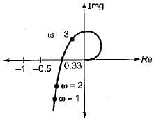
What is the approximate value of gain margin in the Nyquist diagram shown below?
Detailed Solution for Test: Frequency Domain Analysis of Control Systems- 3 - Question 16

At ω = ωgc,

(Using Nyquist diagram)
∴ 

Test: Frequency Domain Analysis of Control Systems- 3 - Question 17

 The magnitude-frequency response of a control system is given in figure below:
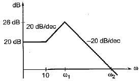
The values of ω1 and ω2 are respectively

Detailed Solution for Test: Frequency Domain Analysis of Control Systems- 3 - Question 17

Number of decade change from first break frequency

Now,

Now, no. of decade change from break frequency

∴ 
or, 
ω2 = 400 rad/s

Test: Frequency Domain Analysis of Control Systems- 3 - Question 18

Match List-I with List-Il and select the correct answer using the codes given below the lists:
List-I
A. Resonant peak
B. Damped natural frequency (rad/s)
C. Resonant frequency (rad/s)
D. Peak overshoot
List - II
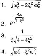
Codes:
    A B C D
(a) 3 4 1 2
(b) 3 1 4 2
(c) 2 4 1 3
(d) 2 1 4 3

Test: Frequency Domain Analysis of Control Systems- 3 - Question 19

A second order underdamped system has a damping ratio of 0.8. It is subjected to a sinusoidal input of unit amplitude. It has resonant peak of

Detailed Solution for Test: Frequency Domain Analysis of Control Systems- 3 - Question 19

Resonant frequency is given by

For resonant peak

or,

Since ξ > 0.707, therefore there is no Mr (resonant peak).

Test: Frequency Domain Analysis of Control Systems- 3 - Question 20

Band width is the range of frequencies for which system gain is

Detailed Solution for Test: Frequency Domain Analysis of Control Systems- 3 - Question 20

In signal processing and control theory the bandwidth is the frequency at which the closed-loop system gain drops 3 dB below peak.

From the given options, the system gain must be less than 10 dB.

53 videos|73 docs|40 tests
Information about Test: Frequency Domain Analysis of Control Systems- 3 Page
In this test you can find the Exam questions for Test: Frequency Domain Analysis of Control Systems- 3 solved & explained in the simplest way possible. Besides giving Questions and answers for Test: Frequency Domain Analysis of Control Systems- 3, EduRev gives you an ample number of Online tests for practice

Top Courses for Electrical Engineering (EE)

53 videos|73 docs|40 tests
Download as PDF

Top Courses for Electrical Engineering (EE)