Case Based Questions Test: Moving Charges & Magnetism - Grade 12 MCQ
15 Questions MCQ Test - Case Based Questions Test: Moving Charges & Magnetism

Read the following text and answer the following questions on the basis of the same:
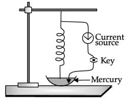
Roget’s spiral: Magnetic effects are generally smaller than electric effects. As a consequence, the force between currents is rather small, because of the smallness of the factor μ. Hence, it is difficult to demonstrate attraction or repulsion between currents. Thus, for 5 A current in each wire at a separation of 1 cm, the force per metre would be 5 × 10⁻⁴ N, which is about 50 mg weight. It would be like pulling a wire by a string going over a pulley to which a 50 mg weight is attached. The displacement of the wire would be quite unnoticeable. With the use of a soft spring, we can increase the effective length of the parallel current and by using mercury, we can make the displacement of even a few mm observable very dramatically. You will also need a constant-current supply giving a constant current of about 5 A. Take a soft spring whose natural period of oscillations is about 0.5–1 s. Hang it vertically and attach a pointed tip to its lower end, as shown in the figure here. Take some mercury in a dish and adjust the spring such that the tip is just above the mercury surface. Take the DC current source, connect one of its terminals to the upper end of the spring and dip the other terminal in mercury. If the tip of the spring touches mercury, the circuit is completed through mercury. Let the DC source be put off to begin with. Let the tip be adjusted so that it just touches the mercury surface. Switch on the constant current supply and watch the fascinating outcome. The spring shrinks with a jerk, the tip comes out of mercury (just by a mm or so), the circuit is broken, the current stops, the spring relaxes and tries to come back to its original position, the tip again touches mercury establishing a current in the circuit and the cycle continues with tick, tick, tick,...

Magnetic effects:
Read the following text and answer the following questions on the basis of the same: Roget’s spiral: Magnetic effects are generally smaller than electric effects. As a consequence, the force between currents is rather small, because of the smallness of the factor μ. Hence, it is difficult to demonstrate attraction or repulsion between currents. Thus, for 5 A current in each wire at a separation of 1 cm, the force per metre would be 5 × 10⁻⁴ N, which is about 50 mg weight. It would be like pulling a wire by a string going over a pulley to which a 50 mg weight is attached. The displacement of the wire would be quite unnoticeable. With the use of a soft spring, we can increase the effective length of the parallel current and by using mercury, we can make the displacement of even a few mm observable very dramatically. You will also need a constant-current supply giving a constant current of about 5 A. Take a soft spring whose natural period of oscillations is about 0.5–1 s. Hang it vertically and attach a pointed tip to its lower end, as shown in the figure here. Take some mercury in a dish and adjust the spring such that the tip is just above the mercury surface. Take the DC current source, connect one of its terminals to the upper end of the spring and dip the other terminal in mercury. If the tip of the spring touches mercury, the circuit is completed through mercury. Let the DC source be put off to begin with. Let the tip be adjusted so that it just touches the mercury surface. Switch on the constant current supply and watch the fascinating outcome. The spring shrinks with a jerk, the tip comes out of mercury (just by a mm or so), the circuit is broken, the current stops, the spring relaxes and tries to come back to its original position, the tip again touches mercury establishing a current in the circuit and the cycle continues with tick, tick, tick,...
Why the spring shrinks in Roget’s spiral ?

Read the following text and answer the following questions on the basis of the same: Roget’s spiral: Magnetic effects are generally smaller than electric effects. As a consequence, the force between currents is rather small, because of the smallness of the factor μ. Hence, it is difficult to demonstrate attraction or repulsion between currents. Thus, for 5 A current in each wire at a separation of 1 cm, the force per metre would be 5 × 10⁻⁴ N, which is about 50 mg weight. It would be like pulling a wire by a string going over a pulley to which a 50 mg weight is attached. The displacement of the wire would be quite unnoticeable. With the use of a soft spring, we can increase the effective length of the parallel current and by using mercury, we can make the displacement of even a few mm observable very dramatically. You will also need a constant-current supply giving a constant current of about 5 A. Take a soft spring whose natural period of oscillations is about 0.5–1 s. Hang it vertically and attach a pointed tip to its lower end, as shown in the figure here. Take some mercury in a dish and adjust the spring such that the tip is just above the mercury surface. Take the DC current source, connect one of its terminals to the upper end of the spring and dip the other terminal in mercury. If the tip of the spring touches mercury, the circuit is completed through mercury. Let the DC source be put off to begin with. Let the tip be adjusted so that it just touches the mercury surface. Switch on the constant current supply and watch the fascinating outcome. The spring shrinks with a jerk, the tip comes out of mercury (just by a mm or so), the circuit is broken, the current stops, the spring relaxes and tries to come back to its original position, the tip again touches mercury establishing a current in the circuit and the cycle continues with tick, tick, tick,...

What else can be used instead of mercury in Roget’s spiral ?
Read the following text and answer the following questions on the basis of the same:
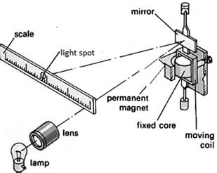
Galvanometer can sense/measure current. Improved mirror galvanometer was developed by William Thomson, later to become Lord Kelvin, in 1858. Thomson intended the instrument to read weak signal currents on very long submarine telegraph cables. The fundamental problems of transmitting/ receiving a signal through a lengthy submarine cable was that the electrical current tended to be very low (as little as 1/100,000th of a standard light bulb). So, it was very difficult to detect it. To solve the problem it was thought that larger amount of electric current would be sent through the line. But Thomson had a different approach. He thought the best response was to devise a device that could read faint signals. The galvanometer, first invented in 1802, was a means of detecting electric current. It consisted of a needle that was deflected by the magnetic field created by the electric current. But the galvanometers of the day couldn't detect the weak signals that came through a long underwater cable. But the improved version of galvanometer was highly sensitive to detect the lowest current. The mirror galvanometer consists of a long fine coil of silk-covered copper wire. In the heart of that coil, within a little air-chamber, a small round mirror is hung by a single fibre of floss silk, with four tiny magnets cemented to its back. A beam of light is thrown from a lamp upon the mirror, and reflected by it upon a white screen or scale a few feet distant, where it forms a bright spot of light; when there is no current on the instrument, the spot of light remains stationary at the zero position on the screen; but the instant a current traverses the long wire of the coil, the suspended magnets twist themselves horizontally out of their former position, the mirror is inclined with them, and the beam of light is deflected along the screen to one side or the other, according to the nature of the current. If a positive electric current gives a deflection to the right of zero, a negative current will give a deflection to the left of zero, and vice versa. The air in the little chamber surrounding the mirror is compressed, so as to act like a cushion, and deaden the movements of the mirror; the mirror is thus prevented from idly swinging about at each deflections.
Improved mirror galvanometer was developed by
Read the following text and answer the following questions on the basis of the same: Galvanometer can sense/measure current. Improved mirror galvanometer was developed by William Thomson, later to become Lord Kelvin, in 1858. Thomson intended the instrument to read weak signal currents on very long submarine telegraph cables. The fundamental problems of transmitting/ receiving a signal through a lengthy submarine cable was that the electrical current tended to be very low (as little as 1/100,000th of a standard light bulb). So, it was very difficult to detect it. To solve the problem it was thought that larger amount of electric current would be sent through the line. But Thomson had a different approach. He thought the best response was to devise a device that could read faint signals. The galvanometer, first invented in 1802, was a means of detecting electric current. It consisted of a needle that was deflected by the magnetic field created by the electric current. But the galvanometers of the day couldn't detect the weak signals that came through a long underwater cable. But the improved version of galvanometer was highly sensitive to detect the lowest current. The mirror galvanometer consists of a long fine coil of silk-covered copper wire. In the heart of that coil, within a little air-chamber, a small round mirror is hung by a single fibre of floss silk, with four tiny magnets cemented to its back. A beam of light is thrown from a lamp upon the mirror, and reflected by it upon a white screen or scale a few feet distant, where it forms a bright spot of light; when there is no current on the instrument, the spot of light remains stationary at the zero position on the screen; but the instant a current traverses the long wire of the coil, the suspended magnets twist themselves horizontally out of their former position, the mirror is inclined with them, and the beam of light is deflected along the screen to one side or the other, according to the nature of the current. If a positive electric current gives a deflection to the right of zero, a negative current will give a deflection to the left of zero, and vice versa. The air in the little chamber surrounding the mirror is compressed, so as to act like a cushion, and deaden the movements of the mirror; the mirror is thus prevented from idly swinging about at each deflections.

The basic principle of galvanometer is
Read the following text and answer the following questions on the basis of the same: Galvanometer can sense/measure current. Improved mirror galvanometer was developed by William Thomson, later to become Lord Kelvin, in 1858. Thomson intended the instrument to read weak signal currents on very long submarine telegraph cables. The fundamental problems of transmitting/ receiving a signal through a lengthy submarine cable was that the electrical current tended to be very low (as little as 1/100,000th of a standard light bulb). So, it was very difficult to detect it. To solve the problem it was thought that larger amount of electric current would be sent through the line. But Thomson had a different approach. He thought the best response was to devise a device that could read faint signals. The galvanometer, first invented in 1802, was a means of detecting electric current. It consisted of a needle that was deflected by the magnetic field created by the electric current. But the galvanometers of the day couldn't detect the weak signals that came through a long underwater cable. But the improved version of galvanometer was highly sensitive to detect the lowest current. The mirror galvanometer consists of a long fine coil of silk-covered copper wire. In the heart of that coil, within a little air-chamber, a small round mirror is hung by a single fibre of floss silk, with four tiny magnets cemented to its back. A beam of light is thrown from a lamp upon the mirror, and reflected by it upon a white screen or scale a few feet distant, where it forms a bright spot of light; when there is no current on the instrument, the spot of light remains stationary at the zero position on the screen; but the instant a current traverses the long wire of the coil, the suspended magnets twist themselves horizontally out of their former position, the mirror is inclined with them, and the beam of light is deflected along the screen to one side or the other, according to the nature of the current. If a positive electric current gives a deflection to the right of zero, a negative current will give a deflection to the left of zero, and vice versa. The air in the little chamber surrounding the mirror is compressed, so as to act like a cushion, and deaden the movements of the mirror; the mirror is thus prevented from idly swinging about at each deflections.

How the idly swinging of the mirror of mirror galvanometer is prevented?
Read the following text and answer the following questions on the basis of the same:
TOROID
A toroid is a coil of insulated or enamelled wire wound on a donut-shaped form made of powdered iron. A toroid is used as an inductor in electronic circuits, especially at low frequencies where comparatively large inductances are necessary. A toroid has more inductance , for a given number of turns, than a solenoid with a core of the same material and similar size. This makes it possible to construct high-inductance coils of reasonable physical size and mass. Toroidal coils of a given inductance can carry more current than solenoidal coils of similar size, because larger-diameter wires can be used, and the total amount of wire is less, reducing the resistance . In a toroid, all the magnetic flux is contained in the core material. This is because the core has no ends from which flux might leak off. The confinement of the flux prevents external magnetic fields from affecting the behaviour of the toroid, and also prevents the magnetic field in the toroid from affecting other components in a circuit. Standard toroidal transformers typically offer a 95% efficiency, while standard laminated transformers typically offer less than a 90% rating. One of the most important differences between a toroidal transformer and a traditional laminated transformer is the absence of gaps. The leakage flux through the gaps contributes to the stray losses in the form of eddy currents (which is also expelled in the form of heat). A toroidal core doesn’t have an air gap. The core is tightly wound . The result is a stable, predictable toroidal core, free from discontinuities and holes. Audible vibration or hum in transformers is caused by vibration of the windings and core layers from the forces between the coil turns and core laminations. The toroidal transformer’s construction helps quiet this noise. In audio, or signal transmitting applications, unwarranted noise will affect sound quality, so a transformer with low audible vibration is ideal. For this reason, many sound system engineers prefer to use a toroidal transformer instead of a traditional laminated transformer.
Toroid is a
Read the following text and answer the following questions on the basis of the same: TOROID
A toroid is a coil of insulated or enamelled wire wound on a donut-shaped form made of powdered iron. A toroid is used as an inductor in electronic circuits, especially at low frequencies where comparatively large inductances are necessary. A toroid has more inductance , for a given number of turns, than a solenoid with a core of the same material and similar size. This makes it possible to construct high-inductance coils of reasonable physical size and mass. Toroidal coils of a given inductance can carry more current than solenoidal coils of similar size, because larger-diameter wires can be used, and the total amount of wire is less, reducing the resistance . In a toroid, all the magnetic flux is contained in the core material. This is because the core has no ends from which flux might leak off. The confinement of the flux prevents external magnetic fields from affecting the behaviour of the toroid, and also prevents the magnetic field in the toroid from affecting other components in a circuit. Standard toroidal transformers typically offer a 95% efficiency, while standard laminated transformers typically offer less than a 90% rating. One of the most important differences between a toroidal transformer and a traditional laminated transformer is the absence of gaps. The leakage flux through the gaps contributes to the stray losses in the form of eddy currents (which is also expelled in the form of heat). A toroidal core doesn’t have an air gap. The core is tightly wound . The result is a stable, predictable toroidal core, free from discontinuities and holes. Audible vibration or hum in transformers is caused by vibration of the windings and core layers from the forces between the coil turns and core laminations. The toroidal transformer’s construction helps quiet this noise. In audio, or signal transmitting applications, unwarranted noise will affect sound quality, so a transformer with low audible vibration is ideal. For this reason, many sound system engineers prefer to use a toroidal transformer instead of a traditional laminated transformer.
Why inductance of solenoid is more than the inductance of a solenoid having same number of turns, core of same material and similar size?
Read the following text and answer the following questions on the basis of the same: TOROID
A toroid is a coil of insulated or enamelled wire wound on a donut-shaped form made of powdered iron. A toroid is used as an inductor in electronic circuits, especially at low frequencies where comparatively large inductances are necessary. A toroid has more inductance , for a given number of turns, than a solenoid with a core of the same material and similar size. This makes it possible to construct high-inductance coils of reasonable physical size and mass. Toroidal coils of a given inductance can carry more current than solenoidal coils of similar size, because larger-diameter wires can be used, and the total amount of wire is less, reducing the resistance . In a toroid, all the magnetic flux is contained in the core material. This is because the core has no ends from which flux might leak off. The confinement of the flux prevents external magnetic fields from affecting the behaviour of the toroid, and also prevents the magnetic field in the toroid from affecting other components in a circuit. Standard toroidal transformers typically offer a 95% efficiency, while standard laminated transformers typically offer less than a 90% rating. One of the most important differences between a toroidal transformer and a traditional laminated transformer is the absence of gaps. The leakage flux through the gaps contributes to the stray losses in the form of eddy currents (which is also expelled in the form of heat). A toroidal core doesn’t have an air gap. The core is tightly wound . The result is a stable, predictable toroidal core, free from discontinuities and holes. Audible vibration or hum in transformers is caused by vibration of the windings and core layers from the forces between the coil turns and core laminations. The toroidal transformer’s construction helps quiet this noise. In audio, or signal transmitting applications, unwarranted noise will affect sound quality, so a transformer with low audible vibration is ideal. For this reason, many sound system engineers prefer to use a toroidal transformer instead of a traditional laminated transformer.
Efficiency of toroidal transformer is around ______ % which is ______ than laminated core transformer.
Read the following text and answer the following questions on the basis of the same: Roget’s spiral: Magnetic effects are generally smaller than electric effects. As a consequence, the force between currents is rather small, because of the smallness of the factor μ. Hence, it is difficult to demonstrate attraction or repulsion between currents. Thus, for 5 A current in each wire at a separation of 1 cm, the force per metre would be 5 × 10⁻⁴ N, which is about 50 mg weight. It would be like pulling a wire by a string going over a pulley to which a 50 mg weight is attached. The displacement of the wire would be quite unnoticeable. With the use of a soft spring, we can increase the effective length of the parallel current and by using mercury, we can make the displacement of even a few mm observable very dramatically. You will also need a constant-current supply giving a constant current of about 5 A. Take a soft spring whose natural period of oscillations is about 0.5–1 s. Hang it vertically and attach a pointed tip to its lower end, as shown in the figure here. Take some mercury in a dish and adjust the spring such that the tip is just above the mercury surface. Take the DC current source, connect one of its terminals to the upper end of the spring and dip the other terminal in mercury. If the tip of the spring touches mercury, the circuit is completed through mercury. Let the DC source be put off to begin with. Let the tip be adjusted so that it just touches the mercury surface. Switch on the constant current supply and watch the fascinating outcome. The spring shrinks with a jerk, the tip comes out of mercury (just by a mm or so), the circuit is broken, the current stops, the spring relaxes and tries to come back to its original position, the tip again touches mercury establishing a current in the circuit and the cycle continues with tick, tick, tick,...

The force 10–3 N,is equivalent to:
Read the following text and answer the following questions on the basis of the same: Roget’s spiral: Magnetic effects are generally smaller than electric effects. As a consequence, the force between currents is rather small, because of the smallness of the factor μ. Hence, it is difficult to demonstrate attraction or repulsion between currents. Thus, for 5 A current in each wire at a separation of 1 cm, the force per metre would be 5 × 10⁻⁴ N, which is about 50 mg weight. It would be like pulling a wire by a string going over a pulley to which a 50 mg weight is attached. The displacement of the wire would be quite unnoticeable. With the use of a soft spring, we can increase the effective length of the parallel current and by using mercury, we can make the displacement of even a few mm observable very dramatically. You will also need a constant-current supply giving a constant current of about 5 A. Take a soft spring whose natural period of oscillations is about 0.5–1 s. Hang it vertically and attach a pointed tip to its lower end, as shown in the figure here. Take some mercury in a dish and adjust the spring such that the tip is just above the mercury surface. Take the DC current source, connect one of its terminals to the upper end of the spring and dip the other terminal in mercury. If the tip of the spring touches mercury, the circuit is completed through mercury. Let the DC source be put off to begin with. Let the tip be adjusted so that it just touches the mercury surface. Switch on the constant current supply and watch the fascinating outcome. The spring shrinks with a jerk, the tip comes out of mercury (just by a mm or so), the circuit is broken, the current stops, the spring relaxes and tries to come back to its original position, the tip again touches mercury establishing a current in the circuit and the cycle continues with tick, tick, tick,...

What are the main 3 components in a Roget’s spiral?
Read the following text and answer the following questions on the basis of the same: Galvanometer can sense/measure current. Improved mirror galvanometer was developed by William Thomson, later to become Lord Kelvin, in 1858. Thomson intended the instrument to read weak signal currents on very long submarine telegraph cables. The fundamental problems of transmitting/ receiving a signal through a lengthy submarine cable was that the electrical current tended to be very low (as little as 1/100,000th of a standard light bulb). So, it was very difficult to detect it. To solve the problem it was thought that larger amount of electric current would be sent through the line. But Thomson had a different approach. He thought the best response was to devise a device that could read faint signals. The galvanometer, first invented in 1802, was a means of detecting electric current. It consisted of a needle that was deflected by the magnetic field created by the electric current. But the galvanometers of the day couldn't detect the weak signals that came through a long underwater cable. But the improved version of galvanometer was highly sensitive to detect the lowest current. The mirror galvanometer consists of a long fine coil of silk-covered copper wire. In the heart of that coil, within a little air-chamber, a small round mirror is hung by a single fibre of floss silk, with four tiny magnets cemented to its back. A beam of light is thrown from a lamp upon the mirror, and reflected by it upon a white screen or scale a few feet distant, where it forms a bright spot of light; when there is no current on the instrument, the spot of light remains stationary at the zero position on the screen; but the instant a current traverses the long wire of the coil, the suspended magnets twist themselves horizontally out of their former position, the mirror is inclined with them, and the beam of light is deflected along the screen to one side or the other, according to the nature of the current. If a positive electric current gives a deflection to the right of zero, a negative current will give a deflection to the left of zero, and vice versa. The air in the little chamber surrounding the mirror is compressed, so as to act like a cushion, and deaden the movements of the mirror; the mirror is thus prevented from idly swinging about at each deflections.

Mirror galvanometer was primarily used to
Read the following text and answer the following questions on the basis of the same: Galvanometer can sense/measure current. Improved mirror galvanometer was developed by William Thomson, later to become Lord Kelvin, in 1858. Thomson intended the instrument to read weak signal currents on very long submarine telegraph cables. The fundamental problems of transmitting/ receiving a signal through a lengthy submarine cable was that the electrical current tended to be very low (as little as 1/100,000th of a standard light bulb). So, it was very difficult to detect it. To solve the problem it was thought that larger amount of electric current would be sent through the line. But Thomson had a different approach. He thought the best response was to devise a device that could read faint signals. The galvanometer, first invented in 1802, was a means of detecting electric current. It consisted of a needle that was deflected by the magnetic field created by the electric current. But the galvanometers of the day couldn't detect the weak signals that came through a long underwater cable. But the improved version of galvanometer was highly sensitive to detect the lowest current. The mirror galvanometer consists of a long fine coil of silk-covered copper wire. In the heart of that coil, within a little air-chamber, a small round mirror is hung by a single fibre of floss silk, with four tiny magnets cemented to its back. A beam of light is thrown from a lamp upon the mirror, and reflected by it upon a white screen or scale a few feet distant, where it forms a bright spot of light; when there is no current on the instrument, the spot of light remains stationary at the zero position on the screen; but the instant a current traverses the long wire of the coil, the suspended magnets twist themselves horizontally out of their former position, the mirror is inclined with them, and the beam of light is deflected along the screen to one side or the other, according to the nature of the current. If a positive electric current gives a deflection to the right of zero, a negative current will give a deflection to the left of zero, and vice versa. The air in the little chamber surrounding the mirror is compressed, so as to act like a cushion, and deaden the movements of the mirror; the mirror is thus prevented from idly swinging about at each deflections.

The mirror galvanometer consists of
Read the following text and answer the following questions on the basis of the same:
TOROID
A toroid is a coil of insulated or enamelled wire wound on a donut-shaped form made of powdered iron. A toroid is used as an inductor in electronic circuits, especially at low frequencies where comparatively large inductances are necessary. A toroid has more inductance , for a given number of turns, than a solenoid with a core of the same material and similar size. This makes it possible to construct high-inductance coils of reasonable physical size and mass. Toroidal coils of a given inductance can carry more current than solenoidal coils of similar size, because larger-diameter wires can be used, and the total amount of wire is less, reducing the resistance . In a toroid, all the magnetic flux is contained in the core material. This is because the core has no ends from which flux might leak off. The confinement of the flux prevents external magnetic fields from affecting the behaviour of the toroid, and also prevents the magnetic field in the toroid from affecting other components in a circuit. Standard toroidal transformers typically offer a 95% efficiency, while standard laminated transformers typically offer less than a 90% rating. One of the most important differences between a toroidal transformer and a traditional laminated transformer is the absence of gaps. The leakage flux through the gaps contributes to the stray losses in the form of eddy currents (which is also expelled in the form of heat). A toroidal core doesn’t have an air gap. The core is tightly wound . The result is a stable, predictable toroidal core, free from discontinuities and holes. Audible vibration or hum in transformers is caused by vibration of the windings and core layers from the forces between the coil turns and core laminations. The toroidal transformer’s construction helps quiet this noise. In audio, or signal transmitting applications, unwarranted noise will affect sound quality, so a transformer with low audible vibration is ideal. For this reason, many sound system engineers prefer to use a toroidal transformer instead of a traditional laminated transformer.
A toroid has _____ inductance, for a given number of turns, than a solenoid with a core of the same material and similar size.
Read the following text and answer the following questions on the basis of the same:
TOROID
A toroid is a coil of insulated or enamelled wire wound on a donut-shaped form made of powdered iron. A toroid is used as an inductor in electronic circuits, especially at low frequencies where comparatively large inductances are necessary. A toroid has more inductance , for a given number of turns, than a solenoid with a core of the same material and similar size. This makes it possible to construct high-inductance coils of reasonable physical size and mass. Toroidal coils of a given inductance can carry more current than solenoidal coils of similar size, because larger-diameter wires can be used, and the total amount of wire is less, reducing the resistance . In a toroid, all the magnetic flux is contained in the core material. This is because the core has no ends from which flux might leak off. The confinement of the flux prevents external magnetic fields from affecting the behaviour of the toroid, and also prevents the magnetic field in the toroid from affecting other components in a circuit. Standard toroidal transformers typically offer a 95% efficiency, while standard laminated transformers typically offer less than a 90% rating. One of the most important differences between a toroidal transformer and a traditional laminated transformer is the absence of gaps. The leakage flux through the gaps contributes to the stray losses in the form of eddy currents (which is also expelled in the form of heat). A toroidal core doesn’t have an air gap. The core is tightly wound . The result is a stable, predictable toroidal core, free from discontinuities and holes. Audible vibration or hum in transformers is caused by vibration of the windings and core layers from the forces between the coil turns and core laminations. The toroidal transformer’s construction helps quiet this noise. In audio, or signal transmitting applications, unwarranted noise will affect sound quality, so a transformer with low audible vibration is ideal. For this reason, many sound system engineers prefer to use a toroidal transformer instead of a traditional laminated transformer.
Why sound system engineers prefer to use toroidal transformer?


Important Questions for Case Based Questions Test: Moving Charges & Magnetism
Case Based Questions Test: Moving Charges & Magnetism MCQs with Answers
Online Tests for Case Based Questions Test: Moving Charges & Magnetism
|
© EduRev
|
Education Revolution
|


|


