Case Based Questions Test: Electromagnetic Induction - Grade 12 MCQ
15 Questions MCQ Test - Case Based Questions Test: Electromagnetic Induction

Read the following text and answer the following questions on the basis of the same:
Bottle Dynamo: A bottle dynamo is a small generator to generate electricity to power the bicycle light. Is is not a dynamo. Dynamo generates DC but a bottle dynamo generates AC. Newer models are now available with a rectifier. The available DC can power the light and small electronic gadgets. This is also known as sidewall generator since it operates using a roller placed on the sidewall of bicycle tyre. When the bicycle is in motion, the dynamo roller is engaged and electricity is generated as the tyre spins the roller. When engaged, a dynamo requires the bicycle rider to exert more effort to maintain a given speed than would otherwise be necessary when the dynamo is not present or disengaged. Bottle dynamos can be completely disengaged during day time when cycle light is not in use. In wet conditions, the roller on a bottle dynamo can slip against the surface of the tyre, which interrupts the electricity generated. This cause the lights to go out intermittently.

Why bottle dynamo is not a dynamo?
Read the following text and answer the following questions on the basis of the same:
Bottle Dynamo: A bottle dynamo is a small generator to generate electricity to power the bicycle light. Is is not a dynamo. Dynamo generates DC but a bottle dynamo generates AC. Newer models are now available with a rectifier. The available DC can power the light and small electronic gadgets. This is also known as sidewall generator since it operates using a roller placed on the sidewall of bicycle tyre. When the bicycle is in motion, the dynamo roller is engaged and electricity is generated as the tyre spins the roller. When engaged, a dynamo requires the bicycle rider to exert more effort to maintain a given speed than would otherwise be necessary when the dynamo is not present or disengaged. Bottle dynamos can be completely disengaged during day time when cycle light is not in use. In wet conditions, the roller on a bottle dynamo can slip against the surface of the tyre, which interrupts the electricity generated. This cause the lights to go out intermittently.

Bottle generator generates electricity:

Read the following text and answer the following questions on the basis of the same:
Bottle Dynamo: A bottle dynamo is a small generator to generate electricity to power the bicycle light. Is is not a dynamo. Dynamo generates DC but a bottle dynamo generates AC. Newer models are now available with a rectifier. The available DC can power the light and small electronic gadgets. This is also known as sidewall generator since it operates using a roller placed on the sidewall of bicycle tyre. When the bicycle is in motion, the dynamo roller is engaged and electricity is generated as the tyre spins the roller. When engaged, a dynamo requires the bicycle rider to exert more effort to maintain a given speed than would otherwise be necessary when the dynamo is not present or disengaged. Bottle dynamos can be completely disengaged during day time when cycle light is not in use. In wet conditions, the roller on a bottle dynamo can slip against the surface of the tyre, which interrupts the electricity generated. This cause the lights to go out intermittently.

Which one of the following is not an advantages of newer model of bottle dynamo?
Read the following text and answer the following questions on the basis of the same:
Electromagnetic damping: Take two hollow thin cylindrical pipes of equal internal diameters made of aluminium and PVC, respectively. Fix them vertically with clamps on retort stands. Take a small cylindrical magnet having diameter slightly smaller than the inner diameter of the pipes and drop it through each pipe in such a way that the magnet does not touch the sides of the pipes during its fall. You will observe that the magnet dropped through the PVC pipe takes the same time to come out of the pipe as it would take when dropped through the same height without the pipe. Now instead of PVC pipe use an aluminium pipe. Note the time it takes to come out of the pipe in each case. You will see that the magnet takes much longer time in the case of aluminium pipe. Why is it so ? It is due to the eddy currents that are generated in the aluminium pipe which oppose the change in magnetic flux, i.e., the motion of the magnet. The retarding force due to the eddy currents inhibits the motion of the magnet. Such phenomena are referred to as electromagnetic damping. Note that eddy currents are not generated in PVC pipe as its material is an insulator whereas aluminium is a conductor. This effect was discovered by physicist Foucault (1819-1868).
Eddy current is generated in a:
Read the following text and answer the following questions on the basis of the same:
Electromagnetic damping: Take two hollow thin cylindrical pipes of equal internal diameters made of aluminium and PVC, respectively. Fix them vertically with clamps on retort stands. Take a small cylindrical magnet having diameter slightly smaller than the inner diameter of the pipes and drop it through each pipe in such a way that the magnet does not touch the sides of the pipes during its fall. You will observe that the magnet dropped through the PVC pipe takes the same time to come out of the pipe as it would take when dropped through the same height without the pipe. Now instead of PVC pipe use an aluminium pipe. Note the time it takes to come out of the pipe in each case. You will see that the magnet takes much longer time in the case of aluminium pipe. Why is it so ? It is due to the eddy currents that are generated in the aluminium pipe which oppose the change in magnetic flux, i.e., the motion of the magnet. The retarding force due to the eddy currents inhibits the motion of the magnet. Such phenomena are referred to as electromagnetic damping. Note that eddy currents are not generated in PVC pipe as its material is an insulator whereas aluminium is a conductor. This effect was discovered by physicist Foucault (1819-1868).
What is electromagnetic damping?
Read the following text and answer the following questions on the basis of the same:
Electromagnetic damping: Take two hollow thin cylindrical pipes of equal internal diameters made of aluminium and PVC, respectively. Fix them vertically with clamps on retort stands. Take a small cylindrical magnet having diameter slightly smaller than the inner diameter of the pipes and drop it through each pipe in such a way that the magnet does not touch the sides of the pipes during its fall. You will observe that the magnet dropped through the PVC pipe takes the same time to come out of the pipe as it would take when dropped through the same height without the pipe. Now instead of PVC pipe use an aluminium pipe. Note the time it takes to come out of the pipe in each case. You will see that the magnet takes much longer time in the case of aluminium pipe. Why is it so ? It is due to the eddy currents that are generated in the aluminium pipe which oppose the change in magnetic flux, i.e., the motion of the magnet. The retarding force due to the eddy currents inhibits the motion of the magnet. Such phenomena are referred to as electromagnetic damping. Note that eddy currents are not generated in PVC pipe as its material is an insulator whereas aluminium is a conductor. This effect was discovered by physicist Foucault (1819-1868).
A piece of wood and a bar magnet of same dimension is dropped through an aluminium pipe. Which of the following statements is true?
Read the following text and answer the following questions on the basis of the same:
Spark coil
The principle of electromagnetic induction was discovered by Michael Faraday in 1831. Induction coils were used widely in electrical experiments and for medical therapy during the last half of the 19th century, eventually leading to the development of radio in the 1890's. The spark coil designed on the principle of electromagnetic induction was the heart of the earliest radio transmitters. Marconi used a spark coil designed by Heinrich Rhumkorff in his early experiments. An induction coil or "spark coil" is a type of electrical transformer used to produce high-voltage pulses from a low-voltage (DC) supply. To create the flux changes necessary to induce voltage in the secondary coil, the direct current in the primary coil is repeatedly interrupted by a vibrating mechanical contact called interrupter.
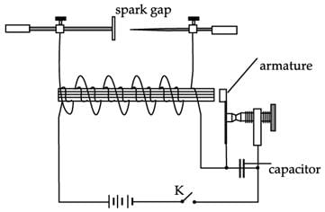
The spark scoil consists of two coils of insulated wire wound around a common iron core. One coil, called the primary coil, is made from relatively few (tens or hundreds) turns of coarse wire. The other coil, the secondary coil typically consists of up to a million turns of fine wire (up to 40 gauge). An electric current is passed through the primary, creating a magnetic field. Because of the common core, most of the primary's flux couples with the secondary. When the primary current is suddenly interrupted, the magnetic field rapidly collapses. This causes a high voltage pulse to be developed across the secondary terminals due to electromagnetic induction. Because of the large number of turns in the secondary coil, the secondary voltage pulse is typically many thousands of volts. This voltage is sufficient to create an electric spark, to jump across an air gap separating the secondary's output terminals. For this reason, this induction coils are also called spark coils. To operate the coil continually, the DC supply current must be repeatedly connected and disconnected. To do that, a magnetically activated vibrating arm called an interrupter is used which rapidly connects and breaks the current flowing into the primary coil. The interrupter is mounted on the end of the coil next to the iron core. When the power is turned on, the produced magnetic field attracts the armature. When the armature has moved far enough, contacts in the primary circuit breaks and disconnects the primary current. Disconnecting the current causes the magnetic field to collapse and create the spark. A short time later the contacts reconnect, and the process repeats. An arc which may form at the interrupter contacts is undesirable. To prevent this, a capacitor of 0.5 to 15 μF is connected across the primary coil.
The heart of the radio transmitters of Marconi was a
Read the following text and answer the following questions on the basis of the same:
Spark coil The principle of electromagnetic induction was discovered by Michael Faraday in 1831. Induction coils were used widely in electrical experiments and for medical therapy during the last half of the 19th century, eventually leading to the development of radio in the 1890's. The spark coil designed on the principle of electromagnetic induction was the heart of the earliest radio transmitters. Marconi used a spark coil designed by Heinrich Rhumkorff in his early experiments. An induction coil or "spark coil" is a type of electrical transformer used to produce high-voltage pulses from a low-voltage (DC) supply. To create the flux changes necessary to induce voltage in the secondary coil, the direct current in the primary coil is repeatedly interrupted by a vibrating mechanical contact called interrupter.

The spark scoil consists of two coils of insulated wire wound around a common iron core. One coil, called the primary coil, is made from relatively few (tens or hundreds) turns of coarse wire. The other coil, the secondary coil typically consists of up to a million turns of fine wire (up to 40 gauge). An electric current is passed through the primary, creating a magnetic field. Because of the common core, most of the primary's flux couples with the secondary. When the primary current is suddenly interrupted, the magnetic field rapidly collapses. This causes a high voltage pulse to be developed across the secondary terminals due to electromagnetic induction. Because of the large number of turns in the secondary coil, the secondary voltage pulse is typically many thousands of volts. This voltage is sufficient to create an electric spark, to jump across an air gap separating the secondary's output terminals. For this reason, this induction coils are also called spark coils. To operate the coil continually, the DC supply current must be repeatedly connected and disconnected. To do that, a magnetically activated vibrating arm called an interrupter is used which rapidly connects and breaks the current flowing into the primary coil. The interrupter is mounted on the end of the coil next to the iron core. When the power is turned on, the produced magnetic field attracts the armature. When the armature has moved far enough, contacts in the primary circuit breaks and disconnects the primary current. Disconnecting the current causes the magnetic field to collapse and create the spark. A short time later the contacts reconnect, and the process repeats. An arc which may form at the interrupter contacts is undesirable. To prevent this, a capacitor of 0.5 to 15 μF is connected across the primary coil.
Which of the following statements is correct?
Read the following text and answer the following questions on the basis of the same: Spark coil The principle of electromagnetic induction was discovered by Michael Faraday in 1831. Induction coils were used widely in electrical experiments and for medical therapy during the last half of the 19th century, eventually leading to the development of radio in the 1890's. The spark coil designed on the principle of electromagnetic induction was the heart of the earliest radio transmitters. Marconi used a spark coil designed by Heinrich Rhumkorff in his early experiments. An induction coil or "spark coil" is a type of electrical transformer used to produce high-voltage pulses from a low-voltage (DC) supply. To create the flux changes necessary to induce voltage in the secondary coil, the direct current in the primary coil is repeatedly interrupted by a vibrating mechanical contact called interrupter.

The spark scoil consists of two coils of insulated wire wound around a common iron core. One coil, called the primary coil, is made from relatively few (tens or hundreds) turns of coarse wire. The other coil, the secondary coil typically consists of up to a million turns of fine wire (up to 40 gauge). An electric current is passed through the primary, creating a magnetic field. Because of the common core, most of the primary's flux couples with the secondary. When the primary current is suddenly interrupted, the magnetic field rapidly collapses. This causes a high voltage pulse to be developed across the secondary terminals due to electromagnetic induction. Because of the large number of turns in the secondary coil, the secondary voltage pulse is typically many thousands of volts. This voltage is sufficient to create an electric spark, to jump across an air gap separating the secondary's output terminals. For this reason, this induction coils are also called spark coils. To operate the coil continually, the DC supply current must be repeatedly connected and disconnected. To do that, a magnetically activated vibrating arm called an interrupter is used which rapidly connects and breaks the current flowing into the primary coil. The interrupter is mounted on the end of the coil next to the iron core. When the power is turned on, the produced magnetic field attracts the armature. When the armature has moved far enough, contacts in the primary circuit breaks and disconnects the primary current. Disconnecting the current causes the magnetic field to collapse and create the spark. A short time later the contacts reconnect, and the process repeats. An arc which may form at the interrupter contacts is undesirable. To prevent this, a capacitor of 0.5 to 15 μF is connected across the primary coil.
What is the function of interrupter in a spark coil?
Read the following text and answer the following questions on the basis of the same:
Bottle Dynamo: A bottle dynamo is a small generator to generate electricity to power the bicycle light. It is not a dynamo. Dynamo generates DC but a bottle dynamo generates AC. Newer models are now available with a rectifier. The available DC can power the light and small electronic gadgets. This is also known as a sidewall generator since it operates using a roller placed on the sidewall of bicycle tyre. When the bicycle is in motion, the dynamo roller is engaged and electricity is generated as the tyre spins the roller. When engaged, a dynamo requires the bicycle rider to exert more effort to maintain a given speed than would otherwise be necessary when the dynamo is not present or disengaged. Bottle dynamos can be completely disengaged during day time when cycle light is not in use. In wet conditions, the roller on a bottle dynamo can slip against the surface of the tyre, which interrupts the electricity generated. This cause the lights to go out intermittently.

Can you recharge the battery of your mobile phone with the help of bottle dynamo?
Read the following text and answer the following questions on the basis of the same:
Bottle Dynamo: A bottle dynamo is a small generator to generate electricity to power the bicycle light. It is not a dynamo. Dynamo generates DC but a bottle dynamo generates AC. Newer models are now available with a rectifier. The available DC can power the light and small electronic gadgets. This is also known as a sidewall generator since it operates using a roller placed on the sidewall of bicycle tyre. When the bicycle is in motion, the dynamo roller is engaged and electricity is generated as the tyre spins the roller. When engaged, a dynamo requires the bicycle rider to exert more effort to maintain a given speed than would otherwise be necessary when the dynamo is not present or disengaged. Bottle dynamos can be completely disengaged during day time when cycle light is not in use. In wet conditions, the roller on a bottle dynamo can slip against the surface of the tyre, which interrupts the electricity generated. This cause the lights to go out intermittently.

Bulb of bicycle light glows:
Read the following text and answer the following questions on the basis of the same: Electromagnetic damping: Take two hollow thin cylindrical pipes of equal internal diameters made of aluminium and PVC, respectively. Fix them vertically with clamps on retort stands. Take a small cylindrical magnet having diameter slightly smaller than the inner diameter of the pipes and drop it through each pipe in such a way that the magnet does not touch the sides of the pipes during its fall. You will observe that the magnet dropped through the PVC pipe takes the same time to come out of the pipe as it would take when dropped through the same height without the pipe. Now instead of PVC pipe use an aluminium pipe. Note the time it takes to come out of the pipe in each case. You will see that the magnet takes much longer time in the case of aluminium pipe. Why is it so ? It is due to the eddy currents that are generated in the aluminium pipe which oppose the change in magnetic flux, i.e., the motion of the magnet. The retarding force due to the eddy currents inhibits the motion of the magnet. Such phenomena are referred to as electromagnetic damping. Note that eddy currents are not generated in PVC pipe as its material is an insulator whereas aluminium is a conductor. This effect was discovered by physicist Foucault (1819-1868).
Eddy current was first observed by:
Read the following text and answer the following questions on the basis of the same:
Electromagnetic damping: Take two hollow thin cylindrical pipes of equal internal diameters made of aluminium and PVC, respectively. Fix them vertically with clamps on retort stands. Take a small cylindrical magnet having diameter slightly smaller than the inner diameter of the pipes and drop it through each pipe in such a way that the magnet does not touch the sides of the pipes during its fall. You will observe that the magnet dropped through the PVC pipe takes the same time to come out of the pipe as it would take when dropped through the same height without the pipe. Now instead of PVC pipe use an aluminium pipe. Note the time it takes to come out of the pipe in each case. You will see that the magnet takes much longer time in the case of aluminium pipe. Why is it so ? It is due to the eddy currents that are generated in the aluminium pipe which oppose the change in magnetic flux, i.e., the motion of the magnet. The retarding force due to the eddy currents inhibits the motion of the magnet. Such phenomena are referred to as electromagnetic damping. Note that eddy currents are not generated in PVC pipe as its material is an insulator whereas aluminium is a conductor. This effect was discovered by physicist Foucault (1819-1868).
To observe electromagnetic damping a magnet should be dropped through a metal pipe and:
Read the following text and answer the following questions on the basis of the same:
Spark coil The principle of electromagnetic induction was discovered by Michael Faraday in 1831. Induction coils were used widely in electrical experiments and for medical therapy during the last half of the 19th century, eventually leading to the development of radio in the 1890's. The spark coil designed on the principle of electromagnetic induction was the heart of the earliest radio transmitters. Marconi used a spark coil designed by Heinrich Rhumkorff in his early experiments. An induction coil or "spark coil" is a type of electrical transformer used to produce high-voltage pulses from a low-voltage (DC) supply. To create the flux changes necessary to induce voltage in the secondary coil, the direct current in the primary coil is repeatedly interrupted by a vibrating mechanical contact called interrupter.

The spark scoil consists of two coils of insulated wire wound around a common iron core. One coil, called the primary coil, is made from relatively few (tens or hundreds) turns of coarse wire. The other coil, the secondary coil typically consists of up to a million turns of fine wire (up to 40 gauge). An electric current is passed through the primary, creating a magnetic field. Because of the common core, most of the primary's flux couples with the secondary. When the primary current is suddenly interrupted, the magnetic field rapidly collapses. This causes a high voltage pulse to be developed across the secondary terminals due to electromagnetic induction. Because of the large number of turns in the secondary coil, the secondary voltage pulse is typically many thousands of volts. This voltage is sufficient to create an electric spark, to jump across an air gap separating the secondary's output terminals. For this reason, this induction coils are also called spark coils. To operate the coil continually, the DC supply current must be repeatedly connected and disconnected. To do that, a magnetically activated vibrating arm called an interrupter is used which rapidly connects and breaks the current flowing into the primary coil. The interrupter is mounted on the end of the coil next to the iron core. When the power is turned on, the produced magnetic field attracts the armature. When the armature has moved far enough, contacts in the primary circuit breaks and disconnects the primary current. Disconnecting the current causes the magnetic field to collapse and create the spark. A short time later the contacts reconnect, and the process repeats. An arc which may form at the interrupter contacts is undesirable. To prevent this, a capacitor of 0.5 to 15 μF is connected across the primary coil.
Spark coil is a type of
Read the following text and answer the following questions on the basis of the same: Spark coil The principle of electromagnetic induction was discovered by Michael Faraday in 1831. Induction coils were used widely in electrical experiments and for medical therapy during the last half of the 19th century, eventually leading to the development of radio in the 1890's. The spark coil designed on the principle of electromagnetic induction was the heart of the earliest radio transmitters. Marconi used a spark coil designed by Heinrich Rhumkorff in his early experiments. An induction coil or "spark coil" is a type of electrical transformer used to produce high-voltage pulses from a low-voltage (DC) supply. To create the flux changes necessary to induce voltage in the secondary coil, the direct current in the primary coil is repeatedly interrupted by a vibrating mechanical contact called interrupter.

The spark scoil consists of two coils of insulated wire wound around a common iron core. One coil, called the primary coil, is made from relatively few (tens or hundreds) turns of coarse wire. The other coil, the secondary coil typically consists of up to a million turns of fine wire (up to 40 gauge). An electric current is passed through the primary, creating a magnetic field. Because of the common core, most of the primary's flux couples with the secondary. When the primary current is suddenly interrupted, the magnetic field rapidly collapses. This causes a high voltage pulse to be developed across the secondary terminals due to electromagnetic induction. Because of the large number of turns in the secondary coil, the secondary voltage pulse is typically many thousands of volts. This voltage is sufficient to create an electric spark, to jump across an air gap separating the secondary's output terminals. For this reason, this induction coils are also called spark coils. To operate the coil continually, the DC supply current must be repeatedly connected and disconnected. To do that, a magnetically activated vibrating arm called an interrupter is used which rapidly connects and breaks the current flowing into the primary coil. The interrupter is mounted on the end of the coil next to the iron core. When the power is turned on, the produced magnetic field attracts the armature. When the armature has moved far enough, contacts in the primary circuit breaks and disconnects the primary current. Disconnecting the current causes the magnetic field to collapse and create the spark. A short time later the contacts reconnect, and the process repeats. An arc which may form at the interrupter contacts is undesirable. To prevent this, a capacitor of 0.5 to 15 μF is connected across the primary coil.
Why most of the primary's flux couples with the secondary in spark coil?
Important Questions for Case Based Questions Test: Electromagnetic Induction
Case Based Questions Test: Electromagnetic Induction MCQs with Answers
Online Tests for Case Based Questions Test: Electromagnetic Induction
|
© EduRev
|
Education Revolution
|


|


