Civil Engineering (CE) Exam  >  Civil Engineering (CE) Tests  >  GATE Civil Engineering (CE) 2025 Mock Test Series  >  Test: Trusses -2 - Civil Engineering (CE) MCQ

Test: Trusses -2 - Civil Engineering (CE) MCQ


Test Description

10 Questions MCQ Test GATE Civil Engineering (CE) 2025 Mock Test Series - Test: Trusses -2

Test: Trusses -2 for Civil Engineering (CE) 2024 is part of GATE Civil Engineering (CE) 2025 Mock Test Series preparation. The Test: Trusses -2 questions and answers have been prepared according to the Civil Engineering (CE) exam syllabus.The Test: Trusses -2 MCQs are made for Civil Engineering (CE) 2024 Exam. Find important definitions, questions, notes, meanings, examples, exercises, MCQs and online tests for Test: Trusses -2 below.
Solutions of Test: Trusses -2 questions in English are available as part of our GATE Civil Engineering (CE) 2025 Mock Test Series for Civil Engineering (CE) & Test: Trusses -2 solutions in Hindi for GATE Civil Engineering (CE) 2025 Mock Test Series course. Download more important topics, notes, lectures and mock test series for Civil Engineering (CE) Exam by signing up for free. Attempt Test: Trusses -2 | 10 questions in 30 minutes | Mock test for Civil Engineering (CE) preparation | Free important questions MCQ to study GATE Civil Engineering (CE) 2025 Mock Test Series for Civil Engineering (CE) Exam | Download free PDF with solutions
Test: Trusses -2 - Question 1

The force induced in the vertical member CD of the symmetrical plane truss shown in the figure is
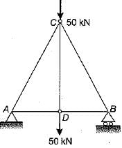
Detailed Solution for Test: Trusses -2 - Question 1

At join D, the equilibrium shows the force in member CD is 50 kN tensile.

Test: Trusses -2 - Question 2

Consider the following Assumptions in the analysis of a plane truss:
1. The individual members are straight.
2. The individual members are connected by frictionless hinges.
3. The loads and reactions acts only at the joints.

Which of the following assumptions are valid?

Detailed Solution for Test: Trusses -2 - Question 2

For plane truss assumptions are:
(i) Weight of all members are neglected. All members are straight.
(ii) All connections are smooth, frictionless pins.
(iii) External loads are applied directly to the pin joints.
(iv) All frames are perfect, hence statically determinate.

1 Crore+ students have signed up on EduRev. Have you? Download the App
Test: Trusses -2 - Question 3

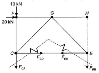
A loaded pin-jointed truss is shown in the given figure. The force in member AC is 
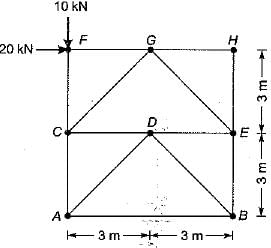
Detailed Solution for Test: Trusses -2 - Question 3

Cutting a section through members CA, CD, DEand EB and taking moment of the upper part about E.

∴ Fca x 6 + 10 x 6 - 20 x 3 = 0
∴ Fca = 0

Test: Trusses -2 - Question 4

What does the Wiiiiot-Mohr diagram yield?

Test: Trusses -2 - Question 5

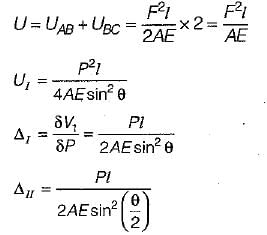
​Which one of the following is the correct statements regarding the force and deflection at point B in trusses I and II shown in the figure?
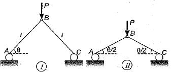
Detailed Solution for Test: Trusses -2 - Question 5

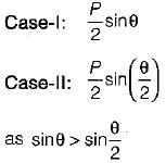
Force in AB or AC [Consider joint B],

So in case I force in members will be less than that in case II.
From symmetry, there will be only vertical deflection of joint B.

Test: Trusses -2 - Question 6

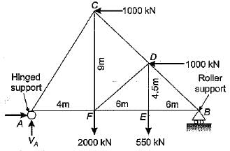
A truss ABC carries two horizontal and two vertical loads, as shown in the figure. The horizontal and vertical components of reactions at A will be
Test: Trusses -2 - Question 7

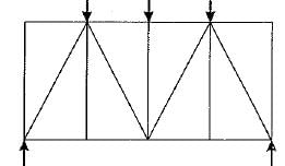
In the plane truss shown below, how many members have zero force?
Detailed Solution for Test: Trusses -2 - Question 7


  • Zero-force member conditions:

    • If two non-collinear members meet at a joint with no external load or support, both are zero-force members.
    • If three members form a truss joint where two are collinear and no load or support is applied, the non-collinear member has zero force.
  • Applying conditions:

    • Identify such joints in the truss diagram.
    • Based on the geometry, 7 members meet the criteria.

Step-by-Step Application:

  1. Left Triangle (Top Joint):

    • Top joint has no external load or support.
    • Two non-collinear members meet here:
      • The diagonal member is zero-force (1 member).
  2. Middle Left Triangle (Top Joint):

    • Similar condition as above. Top joint has no load or support.
    • The diagonal member is zero-force (2nd member).
  3. Middle Right Triangle (Top Joint):

    • Again, top joint with no load or support.
    • The diagonal member is zero-force (3rd member).
  4. Right Triangle (Top Joint):

    • Same condition applies as the left triangle.
    • The diagonal member is zero-force (4th member).
  5. Horizontal Members (Middle):

    • Horizontal members at the middle of triangles connect unloaded joints.
    • These members are zero-force due to symmetry:
      • Two horizontal members are zero-force (5th and 6th members).
  6. Diagonal Member (Bottom Middle Joint):

    • The diagonal member connecting the bottom middle joint is zero-force (7th member).

Final Count:

  • Total 7 zero-force members identified based on the above conditions.

Correct Answer: (c) 7.

Test: Trusses -2 - Question 8

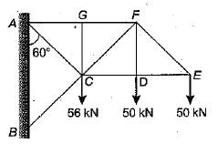
The force in member FD in the given figure is

Test: Trusses -2 - Question 9

In the pin-jointed plane truss shown below, what is the magnitude and nature of force in member BC?

Detailed Solution for Test: Trusses -2 - Question 9

At joint C there is no external force so force in member BC is zero.

Test: Trusses -2 - Question 10

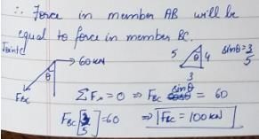
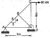
Due to horizontal pull 60 kN at C, what is the force induced in the member AB?
Detailed Solution for Test: Trusses -2 - Question 10


31 docs|280 tests
Information about Test: Trusses -2 Page
In this test you can find the Exam questions for Test: Trusses -2 solved & explained in the simplest way possible. Besides giving Questions and answers for Test: Trusses -2, EduRev gives you an ample number of Online tests for practice

Top Courses for Civil Engineering (CE)

Download as PDF

Top Courses for Civil Engineering (CE)