Electronics and Communication Engineering (ECE) Exam  >  Electronics and Communication Engineering (ECE) Tests  >  GATE ECE (Electronics) Mock Test Series 2025  >  Test: Control System - 1 - Electronics and Communication Engineering (ECE) MCQ

Test: Control System - 1 - Electronics and Communication Engineering (ECE) MCQ


Test Description

15 Questions MCQ Test GATE ECE (Electronics) Mock Test Series 2025 - Test: Control System - 1

Test: Control System - 1 for Electronics and Communication Engineering (ECE) 2025 is part of GATE ECE (Electronics) Mock Test Series 2025 preparation. The Test: Control System - 1 questions and answers have been prepared according to the Electronics and Communication Engineering (ECE) exam syllabus.The Test: Control System - 1 MCQs are made for Electronics and Communication Engineering (ECE) 2025 Exam. Find important definitions, questions, notes, meanings, examples, exercises, MCQs and online tests for Test: Control System - 1 below.
Solutions of Test: Control System - 1 questions in English are available as part of our GATE ECE (Electronics) Mock Test Series 2025 for Electronics and Communication Engineering (ECE) & Test: Control System - 1 solutions in Hindi for GATE ECE (Electronics) Mock Test Series 2025 course. Download more important topics, notes, lectures and mock test series for Electronics and Communication Engineering (ECE) Exam by signing up for free. Attempt Test: Control System - 1 | 15 questions in 45 minutes | Mock test for Electronics and Communication Engineering (ECE) preparation | Free important questions MCQ to study GATE ECE (Electronics) Mock Test Series 2025 for Electronics and Communication Engineering (ECE) Exam | Download free PDF with solutions
Test: Control System - 1 - Question 1

Determine C/R for the system given in figure below. Then put G3 = G1 G2 H2. Now the new

transfer function will be:

Detailed Solution for Test: Control System - 1 - Question 1

Test: Control System - 1 - Question 2

The signal-flow graph shown in figure below has:

Detailed Solution for Test: Control System - 1 - Question 2

Forward paths are:

Loops are:

*Answer can only contain numeric values
Test: Control System - 1 - Question 3

The unit impulse response of a system is h(t) = e-2t, t 0.

For this system, the steady-state value of the output for unit step input is equal to      


Detailed Solution for Test: Control System - 1 - Question 3


and

Test: Control System - 1 - Question 4

A control system has input r(t) and output c(t). If the input is first passed through a block

whose transfer function is a-2s and then applied to the system, the modified output will be

Detailed Solution for Test: Control System - 1 - Question 4


Test: Control System - 1 - Question 5

The open-loop transfer function of a feedback control system is given by G(s)

Find the range of the values of T for stability.

Detailed Solution for Test: Control System - 1 - Question 5

The characteristic equation of the system is

s2 + s(2 — T) + 1 = 0

Routh's array becomes:

The system will be stable if

Test: Control System - 1 - Question 6

If the open-loop transfer function of a feedback system is given by

G(s) H(s) = , then the controid of the asymptotes will be

Detailed Solution for Test: Control System - 1 - Question 6

Poles = 0, —2, —1 + 2j, —1 —2j

Total number of pole, P = 4

Total number of zero, Z = 0
∴           P — Z = 4

∴        

Test: Control System - 1 - Question 7

For the block diagram shown in figure below, the limiting value of k for stability of the inner loop is found to be X < k < Y. The overall system will be stable if and only if

Detailed Solution for Test: Control System - 1 - Question 7

For inner loop:

 let

For outer loop:

Test: Control System - 1 - Question 8

The closed loop transfer function of a control system has the following poles and zeros

Poles                                                       Zeros

P1 =    0.5                                                          Z1 = –7

P2 = –1.0                                                          Z2 = 9

P3 = –5

P4 = —10

The closed loop response can be closely approximated by considering which of the following?

Detailed Solution for Test: Control System - 1 - Question 8

Because of concept of dominant pole. Here P1 and P2 are dominant pole and P3 and P4 are

insignificant poles.

Test: Control System - 1 - Question 9

Match List-I (Type of compensator) with List-II (Polar plot) and select the correct answer using the code given below the lists:

List-I   


1.Phase lead                                   

2. Phase lag                                   

3. Lead-lag                                       


    A B C

(a)123

(b) 132

(c) 213

(d) 231

Test: Control System - 1 - Question 10

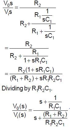
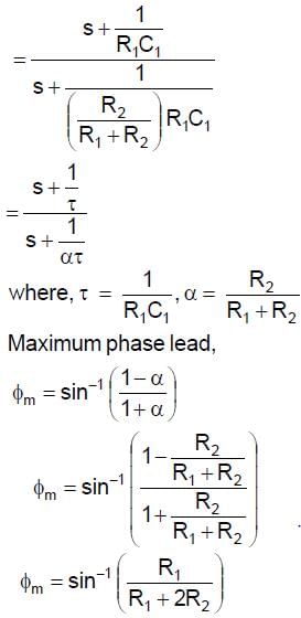
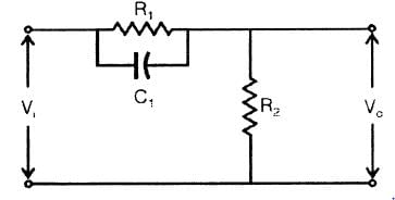
For the given network, the maximum phase lead 4m of Vo with respect to V1 is
Detailed Solution for Test: Control System - 1 - Question 10

Test: Control System - 1 - Question 11

In the Bode-plot of a unity feedback control system, the value of phase of G(j@) at the gain

cross-over frequency is —125°. The phase margin of the system is

Detailed Solution for Test: Control System - 1 - Question 11

φ at ωg C = —125°

Phase-margin (PM) = 180°+ φ

= 180°— 125°

= 55°


Test: Control System - 1 - Question 12

The Nyquist plot for the function is

The condition for stability is given by

Test: Control System - 1 - Question 13

The open-loop transfer function of unity feedback system is G(s) =  . Thes (s + 2) (s + 10)range of k for which closed-loop system is stable.

Detailed Solution for Test: Control System - 1 - Question 13


It is type-1 and order —3 system so the Nyquist plot is

For stability:

Test: Control System - 1 - Question 14

The Bode plot for minimum phase transfer function is:

Detailed Solution for Test: Control System - 1 - Question 14

(a)

  1. In option (a) Bode plot represents - Minimum phase transfer function
  2. In option (b) Bode plot represents - Non-minimum phase transfer function
  3. In option (c) Bode plot represents - All pass transfer function
Test: Control System - 1 - Question 15

For the system shown below the state-space equation is X = A x + B u. The matrix A is

Detailed Solution for Test: Control System - 1 - Question 15

From the SFG

25 docs|263 tests
Information about Test: Control System - 1 Page
In this test you can find the Exam questions for Test: Control System - 1 solved & explained in the simplest way possible. Besides giving Questions and answers for Test: Control System - 1, EduRev gives you an ample number of Online tests for practice
Download as PDF