Test: Signal Flow Graphs - 2 - Electronics and Communication Engineering (ECE) MCQ
10 Questions MCQ Test GATE ECE (Electronics) Mock Test Series 2025 - Test: Signal Flow Graphs - 2
Assertion (A): Signal flow graph is applicable to the linear systems.
Reason (R): Signal flow graph method of finding the transfer function of a system is very simple and does not require any reduction technique.
Reason (R): Signal flow graph method of finding the transfer function of a system is very simple and does not require any reduction technique.
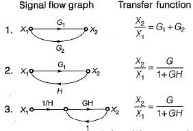
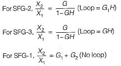
Consider the following three cases of signal flow graph and their corresponding transfer functions:

Q. Which of the above relations is/are correctly matched?

Q. Which of the above relations is/are correctly matched?
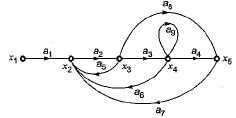
The signal flow graph shown below has M number of forward path and N number of individual loops.

Q. What are the values of M and N ?
The signal flow graph for a certain feedback control system is given below.

Now, consider the following set of equations for the nodes:
- x2= a1x1+a5x3+a6x4+a7x5
- x3=a2x2
- x4=a3x3
- x5=a4x4+a8x3
Q. Which of the above equations are correct?
The gain C(s)/R(s) of the signal flow graph shown below is

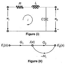
The signal flow graph of the RLC circuit of figure (i) is shown in figure (ii)

The values of G1 and H1 are respectively
Consider the following statements with regards to the signal flow graph shown below.

1. The number of forward paths are 2.
2. The number of forward paths are 5.
3. The number of loops are 3.
4. The number of loops are 5,
5. The number of non-touching loop pairs is 1.
6. The number of non-touching loop pairs is nil.
Q. Which of these statements are correct?
By performing cascading and/or summing/differencing operations using transfer function blocks G1(s) and G2(s), one CANNOT realize a transfer function of the form
|
25 docs|263 tests
|


