Electrical Engineering (EE) Exam  >  Electrical Engineering (EE) Tests  >  GATE Electrical Engineering (EE) Mock Test Series 2025  >  Test: Capacitors & Inductors - 1 - Electrical Engineering (EE) MCQ

Test: Capacitors & Inductors - 1 - Electrical Engineering (EE) MCQ


Test Description

15 Questions MCQ Test GATE Electrical Engineering (EE) Mock Test Series 2025 - Test: Capacitors & Inductors - 1

Test: Capacitors & Inductors - 1 for Electrical Engineering (EE) 2024 is part of GATE Electrical Engineering (EE) Mock Test Series 2025 preparation. The Test: Capacitors & Inductors - 1 questions and answers have been prepared according to the Electrical Engineering (EE) exam syllabus.The Test: Capacitors & Inductors - 1 MCQs are made for Electrical Engineering (EE) 2024 Exam. Find important definitions, questions, notes, meanings, examples, exercises, MCQs and online tests for Test: Capacitors & Inductors - 1 below.
Solutions of Test: Capacitors & Inductors - 1 questions in English are available as part of our GATE Electrical Engineering (EE) Mock Test Series 2025 for Electrical Engineering (EE) & Test: Capacitors & Inductors - 1 solutions in Hindi for GATE Electrical Engineering (EE) Mock Test Series 2025 course. Download more important topics, notes, lectures and mock test series for Electrical Engineering (EE) Exam by signing up for free. Attempt Test: Capacitors & Inductors - 1 | 15 questions in 30 minutes | Mock test for Electrical Engineering (EE) preparation | Free important questions MCQ to study GATE Electrical Engineering (EE) Mock Test Series 2025 for Electrical Engineering (EE) Exam | Download free PDF with solutions
Test: Capacitors & Inductors - 1 - Question 1

 An Inductor works as a ________ circuit for DC supply.

Detailed Solution for Test: Capacitors & Inductors - 1 - Question 1

Induced voltage across an inductor is zero if the current flowing through it is constant, i.e. Inductor works as a short circuit for DC supply.

Test: Capacitors & Inductors - 1 - Question 2

A power factor of a circuit can be improved by placing which, among the following, in a circuit?

Detailed Solution for Test: Capacitors & Inductors - 1 - Question 2

Power factor = Real power / Apparent power = kW/kVA

By adding a capacitor in a circuit, an additional kW load can be added to the system without altering the kVA.

Hence, the power factor is improved.

1 Crore+ students have signed up on EduRev. Have you? Download the App
Test: Capacitors & Inductors - 1 - Question 3

Which among the following equations is incorrect?

Detailed Solution for Test: Capacitors & Inductors - 1 - Question 3
  • Q is directly proportional to V.
  • The constant of proportionality in this case is C, that is, the capacitance.
  • Hence Q=CV. From the given relation we can derive all the equations except for Q = C/V.
Test: Capacitors & Inductors - 1 - Question 4

What is the value of capacitance of a capacitor which has a voltage of 4V and has 16C of charge?

Detailed Solution for Test: Capacitors & Inductors - 1 - Question 4

Q is directly proportional to V.

The constant of proportionality in this case is C, that is, the capacitance.

Hence Q = CV

From the relation,

C = Q/V = 16/4 = 4F

Test: Capacitors & Inductors - 1 - Question 5

What is the total capacitance when two capacitors C1 and C2 are connected in series?

Detailed Solution for Test: Capacitors & Inductors - 1 - Question 5

When capacitors are connected in series, the equivalent capacitance is:
1/Ctotal=1/C1 + 1/C2

therefore,

Ctotal = C1*C2 / (C1+C2)

Test: Capacitors & Inductors - 1 - Question 6

A resistance of 7 ohm is connected in series with an inductance of 31.8mH. The circuit is connected to a 100V 50Hz sinusoidal supply. Calculate the current in the circuit.

Detailed Solution for Test: Capacitors & Inductors - 1 - Question 6

X= 2*π*f*L = 10 ohm

Z= (R2+XL2)

Therefore the total impedance

Z = 12.2 ohm

V = IZ

therefore,

I= V/Z = 100/12.2 = 8.2A

Test: Capacitors & Inductors - 1 - Question 7

The equivalent circuit of the capacitor shown below is:

Detailed Solution for Test: Capacitors & Inductors - 1 - Question 7

Due to initial condition, at t = 0 capacitor will act as a constant voltage source (at t = 0, capacitor acts as short-circuit). Hence, option (d) is correct.

Test: Capacitors & Inductors - 1 - Question 8

The strength of current in 1 Henry inductor changes at a rate of 1 A/sec. The magnitude of energy stored in the inductor after 3 sec is:

Detailed Solution for Test: Capacitors & Inductors - 1 - Question 8

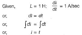
∴ Current in the inductor after 3 sec is: 

1= 3 A

Hence, energy is stored after 3 sec:

Test: Capacitors & Inductors - 1 - Question 9

 The current and voltage profile of an element vs time has been shown in given figure. The element and its value are respectively:

Detailed Solution for Test: Capacitors & Inductors - 1 - Question 9
  • Since V is not proportional to R therefore, the element can’t be a resistor.
  • At t = 5 ms, even if i ≠ 0, the element behaves as a short circuit therefore, the element can’t be a capacitor (since at t = 0 only capacitor behaves as short circuit).
  • The current at t = 0 is zero and at t = 5 ms voltage across the element is zero therefore, the element must be an inductor (at t = 0, an inductor acts as open circuit and at t =∞ it behaves as short circuit).
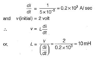
  • From the given voltage and current profile, we have:
Test: Capacitors & Inductors - 1 - Question 10

 Figure shown below exhibits the voltage-time profile of a source to charge a capacitor of 50 μF. The value of charging current in amperes is:

Detailed Solution for Test: Capacitors & Inductors - 1 - Question 10

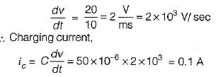
From given figure:

Test: Capacitors & Inductors - 1 - Question 11

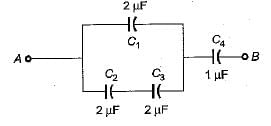
 The equivalent capacitance across the given terminals A-B is:
Detailed Solution for Test: Capacitors & Inductors - 1 - Question 11
  • The equivalent combination of C2 and C3
  • The equivalent combination of this 1 μF and  C1 = 2μF is C1+ 1 μF = 3μF
  • Hence, the equivalent capacitance between terminals A and B is
Test: Capacitors & Inductors - 1 - Question 12

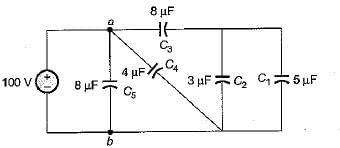
 The charging time required to charge the equivalent capacitance between the given terminals a-b by a steady direct current of constant magnitude of 10 A is given by:
Detailed Solution for Test: Capacitors & Inductors - 1 - Question 12

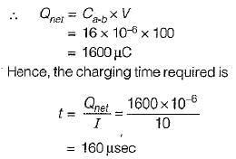
Equivalent capacitance between terminals a-b is:

Test: Capacitors & Inductors - 1 - Question 13

 An ac voltage of 220 V is applied to a pure inductance of 50 H. If the current is 5 A, the instantaneous value of voltage and current will be respectively given by:

Detailed Solution for Test: Capacitors & Inductors - 1 - Question 13

Analysis of AC Circuit with Inductance


  • The problem involves an AC circuit where a 220 V alternating current is applied to a pure inductance of 50 H, resulting in a current of 5 A.

  • In an AC circuit with only inductance, the voltage leads the current by 90 degrees. This phase difference is crucial to determine the instantaneous values of voltage and current.


  •  


Calculating Instantaneous Voltage and Current


  • The root mean square (RMS) voltage is given as 220 V. The RMS value can be converted to peak voltage (Vm) using the formula: Vm = Vrms × √2.

  • Substituting the given values: Vm = 220 V × 1.414 = 311 V (approximately).


  •  


Understanding Current in Inductive Circuits


  • For a pure inductive circuit, the current lags the voltage by 90 degrees. Therefore, if the voltage is described by a sine function, the current will be a sine function shifted by -90 degrees (or equivalently a cosine function).

  • The peak current (Im) is calculated similarly using the RMS current: Im = Irms × √2 = 5 A × 1.414 = 7.07 A.


  •  


Final Formulation


  • The instantaneous voltage can be expressed as: v = 311 sin(314t) Volts.

  • The instantaneous current, considering the phase shift, is: i = 7.07 sin(314t - 90°) Amps.

  •  


Test: Capacitors & Inductors - 1 - Question 14

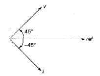
The voltage and current through a circuit element is v= 100 sin (314 t + 45°) volts and i = 10 sin (314 t - 45 ° ) amps.
The type of circuit element and its value will be respectively:

Detailed Solution for Test: Capacitors & Inductors - 1 - Question 14

The phase difference between v and i is: 

Since v leads i therefore, the circuit element is an inductor.

Test: Capacitors & Inductors - 1 - Question 15

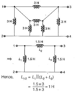
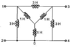
The equivalent inductance for the inductive circuit shown below at terminal “ 1 - 2 ” is:
Detailed Solution for Test: Capacitors & Inductors - 1 - Question 15

Converting the internal star connected inductance to an equivalent delta, the circuit reduces as shown below.

Hence, equivalent circuit becomes as shown below.

25 docs|247 tests
Information about Test: Capacitors & Inductors - 1 Page
In this test you can find the Exam questions for Test: Capacitors & Inductors - 1 solved & explained in the simplest way possible. Besides giving Questions and answers for Test: Capacitors & Inductors - 1, EduRev gives you an ample number of Online tests for practice

Top Courses for Electrical Engineering (EE)

Download as PDF

Top Courses for Electrical Engineering (EE)