Electronics and Communication Engineering (ECE) Exam  >  Electronics and Communication Engineering (ECE) Tests  >  GATE ECE (Electronics) Mock Test Series 2025  >  Test: Networks- 2 - Electronics and Communication Engineering (ECE) MCQ

Test: Networks- 2 - Electronics and Communication Engineering (ECE) MCQ


Test Description

20 Questions MCQ Test GATE ECE (Electronics) Mock Test Series 2025 - Test: Networks- 2

Test: Networks- 2 for Electronics and Communication Engineering (ECE) 2024 is part of GATE ECE (Electronics) Mock Test Series 2025 preparation. The Test: Networks- 2 questions and answers have been prepared according to the Electronics and Communication Engineering (ECE) exam syllabus.The Test: Networks- 2 MCQs are made for Electronics and Communication Engineering (ECE) 2024 Exam. Find important definitions, questions, notes, meanings, examples, exercises, MCQs and online tests for Test: Networks- 2 below.
Solutions of Test: Networks- 2 questions in English are available as part of our GATE ECE (Electronics) Mock Test Series 2025 for Electronics and Communication Engineering (ECE) & Test: Networks- 2 solutions in Hindi for GATE ECE (Electronics) Mock Test Series 2025 course. Download more important topics, notes, lectures and mock test series for Electronics and Communication Engineering (ECE) Exam by signing up for free. Attempt Test: Networks- 2 | 20 questions in 60 minutes | Mock test for Electronics and Communication Engineering (ECE) preparation | Free important questions MCQ to study GATE ECE (Electronics) Mock Test Series 2025 for Electronics and Communication Engineering (ECE) Exam | Download free PDF with solutions
Test: Networks- 2 - Question 1

The Y parameter for total network is

Detailed Solution for Test: Networks- 2 - Question 1

There are two networks connected in parallel. Thus there Y-parameter will be added.

*Answer can only contain numeric values
Test: Networks- 2 - Question 2

in the circuit shown below is


Detailed Solution for Test: Networks- 2 - Question 2


1 Crore+ students have signed up on EduRev. Have you? Download the App
Test: Networks- 2 - Question 3

The value of zin for the circuit shown below is

Detailed Solution for Test: Networks- 2 - Question 3

 Net impedance on primary side of transformer is

*Answer can only contain numeric values
Test: Networks- 2 - Question 4

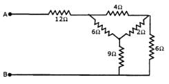
Equivalent resistance across AB is _____Ω


Detailed Solution for Test: Networks- 2 - Question 4

Convert Δ to Y and then use series parallel combination

Test: Networks- 2 - Question 5

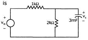
In the circuit given below v,n = u(—t) + u(t) V

Then vc (t) for t > 0 
Detailed Solution for Test: Networks- 2 - Question 5


Test: Networks- 2 - Question 6

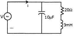
A voltage V = 12√2 cos 5000t V is applied to the circuit shown below.

The current i(t) is
Detailed Solution for Test: Networks- 2 - Question 6


Test: Networks- 2 - Question 7

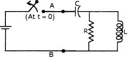
In the circuit shown below, the voltage source has been connected for a long time enough for steady state condition to be reached. At time t = 0, switch S is opened. Then open circuit voltage across AB is
Test: Networks- 2 - Question 8

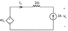
Calculate Vx & Ix in the circuit shown below.

Detailed Solution for Test: Networks- 2 - Question 8

Ix = -2A
Apply KCL
-4Ix + 2Ix + Vx = 0
Vx = 4Ix -2Ix = 2Ix = -4V

Test: Networks- 2 - Question 9

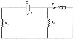
Determine the value of I' in the circuit shown below.

Test: Networks- 2 - Question 10

Determine RMS values of voltage across capacitor (0.25F), current throughcapacitor, if voltage across capacitor is 4 + 4 cos (9t) - 5cos (4t)

Detailed Solution for Test: Networks- 2 - Question 10

Vc = 4 + 4 cos(9t) - 5cos(4t)

= 1/4 {-4(9) sin(9t) + 5(4) sin (4t)} 
⇒ -9 sin(9t) + 5 sin (4t)

RMS value of VL is =


*Answer can only contain numeric values
Test: Networks- 2 - Question 11

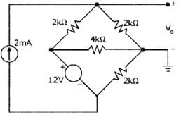
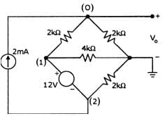
The value of V, in the circuit shown below


Detailed Solution for Test: Networks- 2 - Question 11

V1— V2 =12V................. (1)

At node 0:

 --------(2)

At supernode 1 - 2
(3) 

Solving 1, 2 & 3; Vo = 4.5V; V1 = 5V; V2 = —7V

Test: Networks- 2 - Question 12

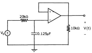
For the circuit shown in figure, find V(t) when Vs = 2sin(500t) V
*Answer can only contain numeric values
Test: Networks- 2 - Question 13

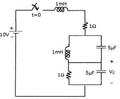
In the circuit shown below, the switch is closed at time t=0. The steady state value of the voltage Vc is_____ V

Detailed Solution for Test: Networks- 2 - Question 13

At steady state inductor short circuit, capacitor is open circuit. Thus voltage Vc is equal to voltage across 1 ohm resistance.

Test: Networks- 2 - Question 14

Which of the following statements are true for the circuit shown below?

1. It is first order with steady state value of 
2. It is second order with steady state value of  V = iV, I = 1A
3. The network function   has one pole I(s)
4. The network function has two poles I(s)

Choose the correct one

Detailed Solution for Test: Networks- 2 - Question 14

Under steady state,


Where V(t) is the voltage across the capacitor

This has a pole at S = -2.

Test: Networks- 2 - Question 15

In the circuit shown below, it is found that the input ac voltage and current are in phase. The value of coupling coefficient K and the dot polarity of the coil PQ are

Detailed Solution for Test: Networks- 2 - Question 15

If input ac voltage and current are in phase then net impedance is equal to zero. Net inductive impedance = Net capacitive impedance

, Thus k = 21 and dot must be at Q so that net inductance =

Test: Networks- 2 - Question 16

For the given circuit, switch closes at t = 0

Detailed Solution for Test: Networks- 2 - Question 16


Test: Networks- 2 - Question 17

The voltage applied to a particular circuit comprising two components connected in series is given by:

V = (30 + 40 sin 103t +25sin2x103t +15sin4x103t) Vand the resulting current is given by

= 0.743 sin (103t + 1.190) + 0.781sin(2x10³t + 0.896) + 0.636sin(4x10³t + 0.559)A

Q. Average power supplied is

Detailed Solution for Test: Networks- 2 - Question 17

Average Power P is given by


P = 0 + 5.523+ 6.099+ 4.044 =15.67W

Test: Networks- 2 - Question 18

The voltage applied to a particular circuit comprising two components connected in series is given by:

V = (30 + 40 sin103t +25sin2x103t +15sin4x103t) Vand the resulting current is given by

= 0.743 sin (103t + 1.190) + 0.781sin(2x10³t + 0.896) + 0.636sin(4x10³t + 0.559)A

Q. Which of the following element is not a part of the circuit?

Detailed Solution for Test: Networks- 2 - Question 18

The expression for the voltage contains a dc component of 30V. However there is no corresponding term in the expression for current. This indicates that one of the components is a capacitor (since in a dc circuit a capacitor offers infinite impedance to a direct current). Since power is delivered to the circuit the other component is a resistor.

Test: Networks- 2 - Question 19

Consider the circuit shown in figure

Q. 

Detailed Solution for Test: Networks- 2 - Question 19

Using current division rule


Test: Networks- 2 - Question 20

Consider the circuit shown in figure

Q. If input current is δ(t), then io (t) (in Amps) will be

Detailed Solution for Test: Networks- 2 - Question 20


25 docs|263 tests
Information about Test: Networks- 2 Page
In this test you can find the Exam questions for Test: Networks- 2 solved & explained in the simplest way possible. Besides giving Questions and answers for Test: Networks- 2, EduRev gives you an ample number of Online tests for practice

Top Courses for Electronics and Communication Engineering (ECE)

Download as PDF

Top Courses for Electronics and Communication Engineering (ECE)