Test: Decoders - Electrical Engineering (EE) MCQ


Test Description

15 Questions MCQ Test GATE Electrical Engineering (EE) Mock Test Series 2025 - Test: Decoders

Test: Decoders for Electrical Engineering (EE) 2024 is part of GATE Electrical Engineering (EE) Mock Test Series 2025 preparation. The Test: Decoders questions and answers have been prepared according to the Electrical Engineering (EE) exam syllabus.The Test: Decoders MCQs are made for Electrical Engineering (EE) 2024 Exam. Find important definitions, questions, notes, meanings, examples, exercises, MCQs and online tests for Test: Decoders below.
Solutions of Test: Decoders questions in English are available as part of our GATE Electrical Engineering (EE) Mock Test Series 2025 for Electrical Engineering (EE) & Test: Decoders solutions in Hindi for GATE Electrical Engineering (EE) Mock Test Series 2025 course. Download more important topics, notes, lectures and mock test series for Electrical Engineering (EE) Exam by signing up for free. Attempt Test: Decoders | 15 questions in 30 minutes | Mock test for Electrical Engineering (EE) preparation | Free important questions MCQ to study GATE Electrical Engineering (EE) Mock Test Series 2025 for Electrical Engineering (EE) Exam | Download free PDF with solutions
Test: Decoders - Question 1

How many 3 × 8 decoders are required to Construct a 4 × 16 decoder?

Detailed Solution for Test: Decoders - Question 1

Concept:

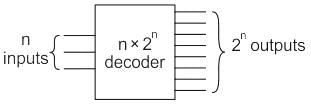
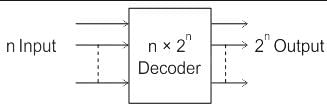
 A decoder is a combinational circuit that converts n lines of input into 2n lines of output.

Decoder expansion

n1 × m1 → n2 × m2

D1             D2

m2/m1= K1

K1/m= K2

K2/m= K3

Number of D2 decoder required is given as:

∑ K = K1 + K2 + K3 + ------ 

Calculation:

Given decoder 1 is 3 × 8 and the second decoder is 4 × 16

16/8 = 2

2/8 = 0

Number of 3 × 8 decoders = 2 + 0

Number of 3 × 8 decoders = 2

Test: Decoders - Question 2

A _________ is a multiple-input, multiple-output logic circuit which converts coded inputs into coded outputs, where the input and output code are different.

Detailed Solution for Test: Decoders - Question 2

Encoder:

An encoder has 2n input lines and n output lines. In the encoder, the output lines generate the binary code corresponding to the input value which is active high.

Decoder:

It is a multi-input and multi-output logic circuit that converts coded inputs into coded outputs where input and output codes are different. Input code has fewer bits than output code. There is one to one mapping from input to output.

Multiplexer:

It is a digital switch. It allows digital information from several sources to be routed onto a single output line. A basic multiplexer has several data input lines and a single output line. The selection of a particular input line is controlled by selection lines. It is many to one mapping and provides the digital equivalent of an analog selector switch. Therefore it is the correct answer

Demultiplexer:

It is a circuit that receives information on a single line and transmits information on one of the 2n output lines. Selection of output line is controlled by values of n selection lines.

1 Crore+ students have signed up on EduRev. Have you? Download the App
Test: Decoders - Question 3

___________ converts binary-coded information to unique outputs such as decimal, octal digits, etc.

Detailed Solution for Test: Decoders - Question 3

Decoder:

  • A decoder is a combinational circuit that has ‘n’ input lines and a maximum of 2n output lines.
  • Decoder converts binary-coded information to unique outputs such as decimal, octal digits, etc.
  • A particular output will be active High depending upon the combination of inputs present when the decoder is enabled.
  • We can, therefore, conclude that a decoder detects a particular code.

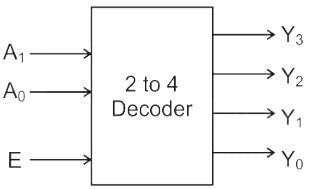
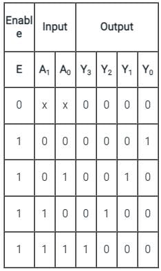
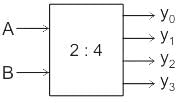
A 2 to 4 decoder is shown in the block diagram below:

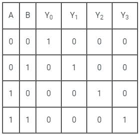
Truth Table:

Application:

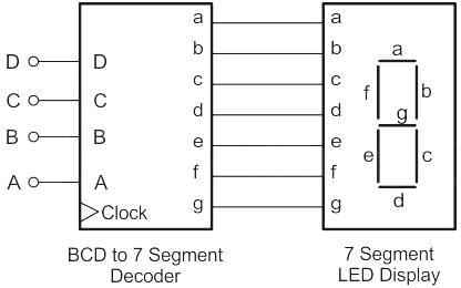
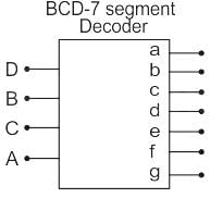
A decoder is used to convert a BCD code to a 7 segment code. This is explained in the following block diagram:

Test: Decoders - Question 4

In a decoder, if the input lines are 4 then number of maximum output lines will be:

Detailed Solution for Test: Decoders - Question 4

Decoder:

The decoder is a combinational ckt, that convert Binary Coded information into Familiar, representation like the decimal, octal, Hexadecimal, etc.

The decoder has ‘n’ no of i/p & less than equal to 2n O/P

i.e., n ≤ 2n
I / P  O / P

For 4 input lines n = 4

Maximum output lines = 24 = 16

Test: Decoders - Question 5

How many 3 × 8 line decoders with an enable input line are needed to construct a 6 × 64 line decoder without using any other logic gate?

Detailed Solution for Test: Decoders - Question 5

Concept:

Decoder expansion

n1 × m1 → n2 × m2

D1             D2

Number of D2 decoder required = ∑ K

m2 / m1 = K1

K1 / m1 = K2

K2 / m1 = K3

Till 0 or 1

Calculation:

Given decoder 1 is 3 × 8 and the second decoder is 6 × 64

64 / 8 = 8

8 / 8 = 1

Number of 3 × 8 decoders = 8 + 1

Number of 3 × 8 decoders = 9

Test: Decoders - Question 6

Direction: Given question consists of two statements, one labeled as the 'Assertion (A)' and the other as 'Reason (R)'. You are to examine these two statements carefully and select the answers to these items using the codes given below.

Assertion (A): A de-multiplexer cannot be used as a decoder.

Reason (R): A de-multiplexer selects one of many outputs, whereas a decoder selects an output corresponding to the coded input.

Detailed Solution for Test: Decoders - Question 6

Decoder:

Generally, a decoder converts a binary number into any other format (decimal, hexadecimal, etc)

Eg: 2 × 4 decoder

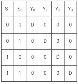
Truth Table:

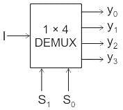
DeMUX: A demultiplexer takes a single input line and produces many output lines.

Now if we put input pin (I) of DeMUX remains at logic 1 and at select pin of DeMUX (S1, S0) we apply i / p (A, B) of decoder then DeMUX will be work as decoder. {I = 1}

Eg:

AB = 00 = S1 S0 ;

Y0 = 1 Y1 = 0 Y2 = 0 Y3 = 0

AB = 10 = S1 S0 ;

Y0 = 0 Y1 = 0 Y2 = 1 Y3 = 0

Test: Decoders - Question 7

The number of input lines in a common BCD to seven segment decoder is _____.

Detailed Solution for Test: Decoders - Question 7
  • In BCD to 7-segment Decoder, the outputs of a digital circuit are often displayed as decimal digits.
  • BCD to 7-segment decoder is a combinational circuit that converts a BCD number into signals that are required for the display of the value of that number on a seven-segment display.
  • The number of input lines is 4. 

Notes:

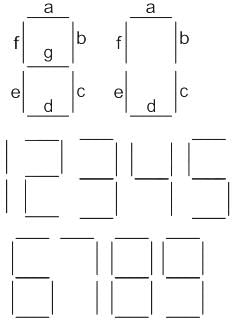
  • The decoder outputs are (a, b, c, d, e, f, g)
  • For the display of the digit 0, segments a, b, c, d, e, f will be lit as shown above.
Test: Decoders - Question 8

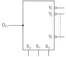
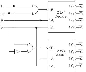
A 1 to 8 demultiplexer with data input Din, address inputs S0, S1, and S2, (with S0  as the LSB) and Y̅0 to Y̅ 7 as the eight de-multiplexed output, is to be designed using two 2 to 4 decoders (with enable input E and address input A0 and A1) as shown in the figure. Din, S0, S1, and S2 are to be connected to P, Q, R, and S but not necessarily in this order. The respective input connections to P, Q, R, and S terminals should be
Detailed Solution for Test: Decoders - Question 8

The given question is the expansion of

2 : 4 decoder to  1 : 8 decoder 

We need to implement 1 : 8 DEMUX.

So, select lines of De-Mux should be mapped to address lines of the decoder.

The LSB of De-Mux should be connected to the LSB of address lines of the decoder

∴ R → S0 

and S→ S1

Input to both the decoder should be same so

∴ P → Din

∴ NOT gate along with OR gate in case to select one decoder at a time so Q → S2 

So,

P → Din

Q → S2

R → S

S→ S1

Hence option (D) is correct

Test: Decoders - Question 9

Find the number of 2 × 1 MUX (multiplexers) required to implement 16 × 1 MUX.

Detailed Solution for Test: Decoders - Question 9

To implement 2n × 1 MUX using 2 × 1 MUX, the total number of 2 × 1 MUX required is (2n - 1).

∴ The number of 2 × 1 multiplexer required to implement 16 × 1 MUX will be:

n = 16 - 1 = 15

Or we can follow the below steps to calculate the same:

1st stage = 16/2 = 8

2nd  stage = 8/2 = 4

3rd stage = 4/2 = 2

4th stage = 2/2 = 1

The sum will give the total number of MUX required to implement 16 × 1 multiplexer using 2 × 1, i.e.

n = 8 + 4 + 2 + 1 = 15

Test: Decoders - Question 10

Which of the following can be represented for decoder?

Detailed Solution for Test: Decoders - Question 10

Combinational circuit in which output depends only on the state of inputs.

Test: Decoders - Question 11

Decoder is constructed from _________

Detailed Solution for Test: Decoders - Question 11

Decoder circuits are constructed from Inverters and AND gates.

Test: Decoders - Question 12

Which of the following is a decoder IC?

Detailed Solution for Test: Decoders - Question 12

8870 is a DTMF decoder circuit, which decodes DTMF tune and produces corresponding output.

Test: Decoders - Question 13

A decoder converts n inputs to __________ outputs.

Detailed Solution for Test: Decoders - Question 13

Decoder is a circuit with n input lines and 2n output lines.

Test: Decoders - Question 14

BCD to seven segment conversion is a ________________

Detailed Solution for Test: Decoders - Question 14

BCD to seven segment code conversion can be treated as a decoding process.

Test: Decoders - Question 15

Which of the following represents a number of output lines for a decoder with 4 input lines?

Detailed Solution for Test: Decoders - Question 15

For n input lined decoder will have 2n output lines.

25 docs|247 tests
Information about Test: Decoders Page
In this test you can find the Exam questions for Test: Decoders solved & explained in the simplest way possible. Besides giving Questions and answers for Test: Decoders, EduRev gives you an ample number of Online tests for practice

Top Courses for Electrical Engineering (EE)

Download as PDF

Top Courses for Electrical Engineering (EE)