Electrical Engineering (EE) Exam  >  Electrical Engineering (EE) Tests  >  GATE Electrical Engineering (EE) Mock Test Series 2025  >  Test: Cathode Ray Oscilloscope - Electrical Engineering (EE) MCQ

Test: Cathode Ray Oscilloscope - Electrical Engineering (EE) MCQ


Test Description

10 Questions MCQ Test GATE Electrical Engineering (EE) Mock Test Series 2025 - Test: Cathode Ray Oscilloscope

Test: Cathode Ray Oscilloscope for Electrical Engineering (EE) 2024 is part of GATE Electrical Engineering (EE) Mock Test Series 2025 preparation. The Test: Cathode Ray Oscilloscope questions and answers have been prepared according to the Electrical Engineering (EE) exam syllabus.The Test: Cathode Ray Oscilloscope MCQs are made for Electrical Engineering (EE) 2024 Exam. Find important definitions, questions, notes, meanings, examples, exercises, MCQs and online tests for Test: Cathode Ray Oscilloscope below.
Solutions of Test: Cathode Ray Oscilloscope questions in English are available as part of our GATE Electrical Engineering (EE) Mock Test Series 2025 for Electrical Engineering (EE) & Test: Cathode Ray Oscilloscope solutions in Hindi for GATE Electrical Engineering (EE) Mock Test Series 2025 course. Download more important topics, notes, lectures and mock test series for Electrical Engineering (EE) Exam by signing up for free. Attempt Test: Cathode Ray Oscilloscope | 10 questions in 30 minutes | Mock test for Electrical Engineering (EE) preparation | Free important questions MCQ to study GATE Electrical Engineering (EE) Mock Test Series 2025 for Electrical Engineering (EE) Exam | Download free PDF with solutions
Test: Cathode Ray Oscilloscope - Question 1

An oscilloscope works similar to _______.

Detailed Solution for Test: Cathode Ray Oscilloscope - Question 1

Oscilloscope is a visual voltmeter with a timer that shows when a voltage changes.
Oscilloscope is defined as an electronic instrument that is used to measure and analyze electronic signals ( waves and pulses) displayed on its screen.
It's functions are:

  1. Shows and calculate the frequency and amplitude of an oscillating signal.
  2. Shows the voltage and time of a particular signal.
  3. Shows the content of the AC voltage or DC voltage of the signal.
Test: Cathode Ray Oscilloscope - Question 2

With _______ testing it is possible to see even smallest distortions clearly on CRO.

Detailed Solution for Test: Cathode Ray Oscilloscope - Question 2

Analysis:
Square Wave:

  • A common wave shape consisting of repeating square pulses.
  • A square wave is a voltage that turns on and off (or goes high and low) at regular intervals.
  • It is a standard wave for testing an amplifiers increase the amplitude of a square wave with minimum distortion.
  • Television, radio and computer circuitry often use square waves for timing signals.

Most oscilloscopes have a square wave reference signal available at a terminal on the front panel used to compensate the probe. Some precautions are -

  • Attach the probe to a vertical channel.
  • Connect the probe tip to the probe compensation.
  • Attach the ground clip of the probe to ground.
  • View the square wave reference signal.
  • Make the proper adjustments on the probe so that the corners of the square wave are square.

Square wave testing it is possible to see even smallest distortions clearly on CRO.

1 Crore+ students have signed up on EduRev. Have you? Download the App
Test: Cathode Ray Oscilloscope - Question 3

Which of the following is used to measure the transmission or reflection of visible light, UV light or infrared light ?

Detailed Solution for Test: Cathode Ray Oscilloscope - Question 3

Spectrophotometer:

  • A spectrophotometer is an analytical instrument used to quantitatively measure the transmission or reflection of visible light, UV light, or infrared light.
  • Spectrophotometers measure intensity as a function of light source wavelength.
  • There is an interaction between electromagnetic radiation (light) and matter in the spectrophotometer.
  • Its applications include measurement of substance concentration such as protein, DNA or RNA, growth of bacterial cells, and enzymatic reactions. Hence option (1) is the correct answer.
Test: Cathode Ray Oscilloscope - Question 4

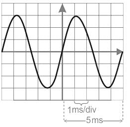
What is the frequency of the sinusoidal signal that occupies five horizontal divisions and three vertical divisions on a CRO for one complete cycle, if the time base is set at 1 ms per division?

Detailed Solution for Test: Cathode Ray Oscilloscope - Question 4

The given time base is set at 1 ms per division.
Also, for one complete cycle, the given sinusoidal signal occupies five horizontal divisions. This is as shown:

The time period of the sinusoid will be:
T = 5 × 1 ms = 5 ms
With 
f = 1/T, the frequency of the sinusoid will be:

f = 200 Hz

Test: Cathode Ray Oscilloscope - Question 5

A CRO can display:

Detailed Solution for Test: Cathode Ray Oscilloscope - Question 5
  • A Cathode Ray Oscilloscope is used for the measurement of AC as well as DC quantities
  • It is used for the calculation of peak to peak voltage, RMS value, duty cycle etc
  • CRO is a very useful and versatile laboratory instrument used for display, measurement and analysis of waveforms
Test: Cathode Ray Oscilloscope - Question 6

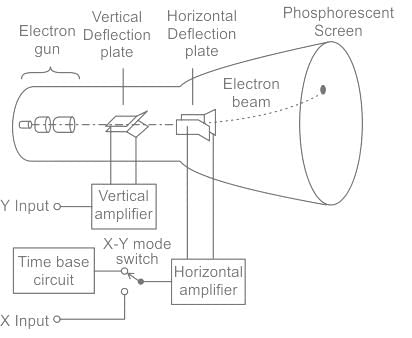
For display of a sine wave in a CRO, what waveform is applied ot the horizontal plates?

Detailed Solution for Test: Cathode Ray Oscilloscope - Question 6

Concept:

  • The oscilloscope is the basic instrument for the study of all types of waveforms.
  • It is capable of generating a graph of an input signal versus time (Voltage-time mode), or a second variable (X-Y mode).
  • It is used to measure: peak voltage, frequency or period, phase difference, pulse-width, delay time, rise time, etc.


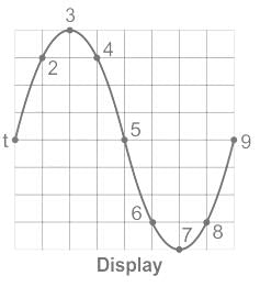
The synchronization of a sine wave (at the vertical plate) with a sawtooth wave (at the horizontal plate) resulting in a graphical display of sine wave on the screen. 

Test: Cathode Ray Oscilloscope - Question 7

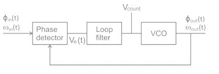
When a PLL is being used as a frequency synthesizer, the output is taken from 

Detailed Solution for Test: Cathode Ray Oscilloscope - Question 7

When a PLL is being used as a frequency synthesizer, the output is taken from ​the VCO output
A PLL is a feedback system that includes a VCO, phase detector, and low pass filter within its loop.
Its purpose is to force the VCO to replicate and track the frequency and phase at the input when in lock.
The PLL is a control system allowing one oscillator to track with another.
It is possible to have a phase offset between input and output, but when locked, the frequencies must exactly track.

Applications

  • Clock generation
  • Frequency synthesizer
  • Clock recovery in a serial data link
Test: Cathode Ray Oscilloscope - Question 8

Lissajous pattern obtained on CRO is used to determine

Detailed Solution for Test: Cathode Ray Oscilloscope - Question 8
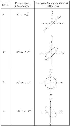
  • A Lissajous figure is a pattern which is displayed on the screen when sinusoidal signals are applied to both horizontal & vertical deflection plates of CRO.
  • These are used to measure the frequency of the given signals and phase difference between the signals.
  • From the shape of the Lissajous pattern displayed on CRO screen information about relative phases of signals and the frequency ratio of signals can be determined.
  • It is not used for precise measurement; it depends on the type of signals.
  • If one frequency is an integral multiple (harmonic) of the other, the pattern will be steady. If not, the figure will not be stationary.

Note: Common Lissajous pattern observed when two signals with different phase angle is applied to the two plates is as shown:

Test: Cathode Ray Oscilloscope - Question 9

For the recording of very fast random signals, the most suitable instrument would be

Detailed Solution for Test: Cathode Ray Oscilloscope - Question 9

Concept:
Sampling Oscilloscope:

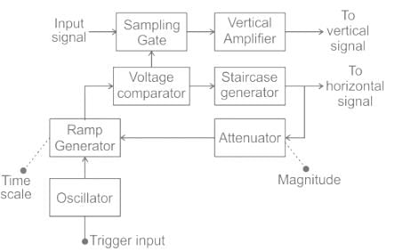
The block diagram of a sampling oscilloscope is as shown:


The sequence of elements from trigger input to horizontal signal is
(b) oscillator
(d) Ramp generator
(a) voltage comparator
(c) staircase generator

Spectrum Analyzer:
The main function of the spectrum analyzer is to obtain the amplitude versus frequency plot from the frequency spectrum under the test.
There are two types of spectrum analyzers: scanning type and non-scanning type. 

Real-time Spectrum Analyzer:

  • It is a non-scanning type spectrum analyzer. 
  • A real-time spectrum analyzer is implemented to have the ability to continuously monitoring the spectrum. 
  • The key to the real-time spectrum analyzer is that it takes successive overlapping FFT samples. and in this way, it provides a 100% probability of intercept, POI for the transient signal.
  • These test instruments are based around an FFT - Fast Fourier Transform spectrum analyzer. This will have a real-time - very fast - digital signal processor capable of processing the entire bandwidth with no gaps.
  • The real-time analyzer will use an ADC - analog to digital converter capable of digitizing the entire bandwidth of the passband.
  • The analyzer needs sufficient capture memory to enable continuous acquisition over the desired measurement period.

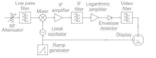
Scanning type Spectrum Analyzer or Superheterodyne Spectrum Analyzer:

  • The swept spectrum analyzer uses the same superheterodyne principle used in many radio receivers as the underlying principle on which its operation depends. The superheterodyne principle uses a mixer and a locally generated local oscillator signal to translate the frequency.
  • The signal entering the front end is translated to another frequency, typically lower in frequency(Down conversion).
  • Using a fixed frequency filter in the intermediate frequency section of the equipment enables high-performance filters to be used, and the analyzer or receiver input frequency can be changed by altering the frequency of the local oscillator signal entering the mixer.
  • The mixing principle used in the analyzer operates in exactly the same manner as it does for a superheterodyne radio.

The spectrum analyzer or sweep / swept spectrum analyzer is a form of a radio receiver with a display at the output indicating the output level. The receiver is tuned or scanned over the required range and the filters are chosen to accept the required signal bandwidth.

Test: Cathode Ray Oscilloscope - Question 10

Which of the following is used to analyze all kinds of matters?

Detailed Solution for Test: Cathode Ray Oscilloscope - Question 10

Concept:
X-ray Diffractometer:

  • Most useful in the characterization of crystalline materials.
  • Ex- Metals, inter-metallic, ceramics, minerals, polymers, and plastics.
  • Used to identify phases, grain size, texture, and crystal imperfections.
  • Rapid and non- destructive to analyze all kinds of matter ranging from fluids to powders and crystals.
  • Lattice parameters and lattice type determinations.

Spectrophotometer:

  • A spectrophotometer is an analytical instrument used to quantitatively measure the transmission or reflection of visible light, UV light or infrared light.
  • Spectrophotometers measure intensity as a function of light source wavelength.
  • There is an interaction between electromagnetic radiation (light) and matter in the spectrophotometer.
  • Its applications include measurement of substance concentration such as protein, DNA or RNA, growth of bacterial cells, and enzymatic reactions.

Electron Microscope:

  • Uses electron beams instead of light.
  • Because of a much lower wavelength of the electron beam than that of light, the resolution is far much better.
  • Used to examine cells, microorganisms, metals, crystals

Spectrum Analyzer:

  • A measuring instrument that displays an electrical signal according to its frequency.
  • Each frequency component contained in the input signal is displayed as a signal level corresponding to that frequency.
25 docs|247 tests
Information about Test: Cathode Ray Oscilloscope Page
In this test you can find the Exam questions for Test: Cathode Ray Oscilloscope solved & explained in the simplest way possible. Besides giving Questions and answers for Test: Cathode Ray Oscilloscope, EduRev gives you an ample number of Online tests for practice

Top Courses for Electrical Engineering (EE)

Download as PDF

Top Courses for Electrical Engineering (EE)