Electronics and Communication Engineering (ECE) Exam  >  Electronics and Communication Engineering (ECE) Tests  >  GATE ECE (Electronics) Mock Test Series 2025  >  Test: Circuit Analysis in the S-Domain - Electronics and Communication Engineering (ECE) MCQ

Test: Circuit Analysis in the S-Domain - Electronics and Communication Engineering (ECE) MCQ


Test Description

20 Questions MCQ Test GATE ECE (Electronics) Mock Test Series 2025 - Test: Circuit Analysis in the S-Domain

Test: Circuit Analysis in the S-Domain for Electronics and Communication Engineering (ECE) 2025 is part of GATE ECE (Electronics) Mock Test Series 2025 preparation. The Test: Circuit Analysis in the S-Domain questions and answers have been prepared according to the Electronics and Communication Engineering (ECE) exam syllabus.The Test: Circuit Analysis in the S-Domain MCQs are made for Electronics and Communication Engineering (ECE) 2025 Exam. Find important definitions, questions, notes, meanings, examples, exercises, MCQs and online tests for Test: Circuit Analysis in the S-Domain below.
Solutions of Test: Circuit Analysis in the S-Domain questions in English are available as part of our GATE ECE (Electronics) Mock Test Series 2025 for Electronics and Communication Engineering (ECE) & Test: Circuit Analysis in the S-Domain solutions in Hindi for GATE ECE (Electronics) Mock Test Series 2025 course. Download more important topics, notes, lectures and mock test series for Electronics and Communication Engineering (ECE) Exam by signing up for free. Attempt Test: Circuit Analysis in the S-Domain | 20 questions in 60 minutes | Mock test for Electronics and Communication Engineering (ECE) preparation | Free important questions MCQ to study GATE ECE (Electronics) Mock Test Series 2025 for Electronics and Communication Engineering (ECE) Exam | Download free PDF with solutions
Test: Circuit Analysis in the S-Domain - Question 1

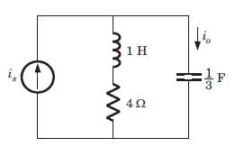
The ratio of the transfer function Io/Is is
Detailed Solution for Test: Circuit Analysis in the S-Domain - Question 1

Io/Is = (s + 4)/ (s + 4 + 3/s) = s(s + 4)/(s + 1)(s + 3).

Test: Circuit Analysis in the S-Domain - Question 2

The voltage across 200 μF capacitor is given by

The steady state voltage across capacitor is

Detailed Solution for Test: Circuit Analysis in the S-Domain - Question 2

Test: Circuit Analysis in the S-Domain - Question 3

The transformed voltage across the 60 μF capacitor is given by

The initial current through capacitor is

Detailed Solution for Test: Circuit Analysis in the S-Domain - Question 3

⇒ 


Test: Circuit Analysis in the S-Domain - Question 4

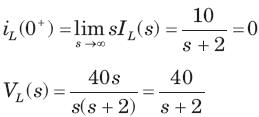
The current through an 4 H inductor is given by

The initial voltage across inductor is

Detailed Solution for Test: Circuit Analysis in the S-Domain - Question 4


Test: Circuit Analysis in the S-Domain - Question 5

The amplifier network shown in fig.is stable if

Detailed Solution for Test: Circuit Analysis in the S-Domain - Question 5


⇒ s2 + (6 - 2K) s + 1 = 0
(6 - 2K) > 0  ⇒ K < 3

Test: Circuit Analysis in the S-Domain - Question 6

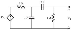
The network shown in fig. is stable if

Detailed Solution for Test: Circuit Analysis in the S-Domain - Question 6

Let v1 be the node voltage of middle node


Test: Circuit Analysis in the S-Domain - Question 7

A circuit has a transfer function with a pole s = -4 and a zero which may be adjusted in position as s= -a The response of this system to a step input has a term of form Ke -4t. The K will be (H= scale factor)

Detailed Solution for Test: Circuit Analysis in the S-Domain - Question 7


Test: Circuit Analysis in the S-Domain - Question 8

A circuit has input vin (t) = cos 2t u(t) V and output io (t) = 2sin 2t u(t) A. The circuit had no internal stored energy at t = 0. The admittance transfer function is

Detailed Solution for Test: Circuit Analysis in the S-Domain - Question 8

Test: Circuit Analysis in the S-Domain - Question 9

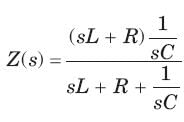
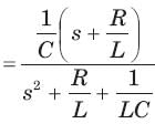
A two terminal network consists of a coil having an inductance L and resistance R shunted by a capacitor C. The poles of the driving point impedance function Z of this network are at  and zero at -1. If Z(0) =1the value of R, L, C are

Detailed Solution for Test: Circuit Analysis in the S-Domain - Question 9

Test: Circuit Analysis in the S-Domain - Question 10

The current response of a network to a unit step input is

The response is

Detailed Solution for Test: Circuit Analysis in the S-Domain - Question 10

The characteristic equation is  s2 (s2 + 11s + 30) = 0 ⇒ s2 (s + 6)(s + 5) = 0
s = -6, -5, Being real and unequal, it is overdamped.

Test: Circuit Analysis in the S-Domain - Question 11

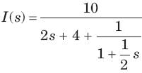
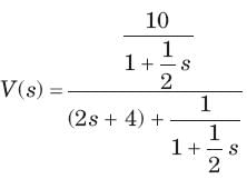
The circuit is shown in fig.

The current ratio transfer function Io/IS  IS
 

Detailed Solution for Test: Circuit Analysis in the S-Domain - Question 11

Test: Circuit Analysis in the S-Domain - Question 12

The circuit is shown in fig.

The response is

Detailed Solution for Test: Circuit Analysis in the S-Domain - Question 12

The characteristic equation is (s+1 (s+3) = 0. Being real and unequal root, it is overdamped response.

Test: Circuit Analysis in the S-Domain - Question 13

The circuit is shown in fig.

If input is is 2u(t) A, the output current io is

Detailed Solution for Test: Circuit Analysis in the S-Domain - Question 13


Test: Circuit Analysis in the S-Domain - Question 14

In the network of Fig. , all initial condition are zero. The damping exhibited by the network is

Detailed Solution for Test: Circuit Analysis in the S-Domain - Question 14

The roots are imaginary so network is underdamped

Test: Circuit Analysis in the S-Domain - Question 15

The voltage response of a network to a unit step input is

The response is

Detailed Solution for Test: Circuit Analysis in the S-Domain - Question 15

The characteristic equation is s(s2 + 8s + 16) = 0 , (s + 4)2 = 0, s = -4, -4

Being real and repeated root, it is critically damped.

Test: Circuit Analysis in the S-Domain - Question 16

The response of an initially relaxed circuit to a signal vs is e-2t u(t). If the signal is changed to  , the response would be

Detailed Solution for Test: Circuit Analysis in the S-Domain - Question 16

 ⇒ 
 ⇒  
 
 ⇒ 

Test: Circuit Analysis in the S-Domain - Question 17

Consider the following statements in the circuit shown in fig.

1. It is a first order circuit with steady state value of vC= 10/3, i = 5/3A

2. It is a second order circuit with steady state of v= 2 V , i = 2 A

3. The network function V(s)/I(s)has one pole.

4. The network function V(s)/I(s) has two poles.

Detailed Solution for Test: Circuit Analysis in the S-Domain - Question 17

It is a second order circuit. In steady state


 It has one pole at s = -2

Test: Circuit Analysis in the S-Domain - Question 18

The network function    represent a

Detailed Solution for Test: Circuit Analysis in the S-Domain - Question 18


The singularity near to origin is pole. So it may be RC impedance or RL admittance function.

Test: Circuit Analysis in the S-Domain - Question 19

The network function  represents an

Detailed Solution for Test: Circuit Analysis in the S-Domain - Question 19

Poles and zero does not interlace on negative real axis so it is not a immittance function

Test: Circuit Analysis in the S-Domain - Question 20

The network function  represents an

Detailed Solution for Test: Circuit Analysis in the S-Domain - Question 20

The singularity nearest to origin is a zero. So it may be RL impedance or RC admittance function. Because of (D) option it is required to check that it is a valid RC admittance function. The poles and zeros interlace along the negative real axis. The residues  are real and positive.

25 docs|263 tests
Information about Test: Circuit Analysis in the S-Domain Page
In this test you can find the Exam questions for Test: Circuit Analysis in the S-Domain solved & explained in the simplest way possible. Besides giving Questions and answers for Test: Circuit Analysis in the S-Domain, EduRev gives you an ample number of Online tests for practice
Download as PDF