Electrical Engineering (EE) Exam  >  Electrical Engineering (EE) Tests  >  GATE Electrical Engineering (EE) Mock Test Series 2025  >  Test: AC Power Analysis- 2 - Electrical Engineering (EE) MCQ

Test: AC Power Analysis- 2 - Electrical Engineering (EE) MCQ


Test Description

10 Questions MCQ Test GATE Electrical Engineering (EE) Mock Test Series 2025 - Test: AC Power Analysis- 2

Test: AC Power Analysis- 2 for Electrical Engineering (EE) 2025 is part of GATE Electrical Engineering (EE) Mock Test Series 2025 preparation. The Test: AC Power Analysis- 2 questions and answers have been prepared according to the Electrical Engineering (EE) exam syllabus.The Test: AC Power Analysis- 2 MCQs are made for Electrical Engineering (EE) 2025 Exam. Find important definitions, questions, notes, meanings, examples, exercises, MCQs and online tests for Test: AC Power Analysis- 2 below.
Solutions of Test: AC Power Analysis- 2 questions in English are available as part of our GATE Electrical Engineering (EE) Mock Test Series 2025 for Electrical Engineering (EE) & Test: AC Power Analysis- 2 solutions in Hindi for GATE Electrical Engineering (EE) Mock Test Series 2025 course. Download more important topics, notes, lectures and mock test series for Electrical Engineering (EE) Exam by signing up for free. Attempt Test: AC Power Analysis- 2 | 10 questions in 30 minutes | Mock test for Electrical Engineering (EE) preparation | Free important questions MCQ to study GATE Electrical Engineering (EE) Mock Test Series 2025 for Electrical Engineering (EE) Exam | Download free PDF with solutions
Test: AC Power Analysis- 2 - Question 1

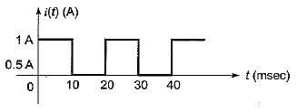
A non-alternating periodic waveform is shown below, It’s from factor is
Detailed Solution for Test: AC Power Analysis- 2 - Question 1

Here, time period is, T = 20 ms; between 10 ms < t < 20 ms, i(t) = 0 A.


Also, 

= 50 x 0.01 =0.5 A

Test: AC Power Analysis- 2 - Question 2

The voltage and current in an a.c, circuit are given by
v = 100 sin 314t; i = 10 sin 314t
The average power in the circuit is

Detailed Solution for Test: AC Power Analysis- 2 - Question 2


∴ Pavg = IR
Now,

(since v and i in phase)

Test: AC Power Analysis- 2 - Question 3

The expression for instantaneous power dissipated in a resistor R connected across a sinusoidal alternating voltage source represented as v = Vm sin ωt is given by

Detailed Solution for Test: AC Power Analysis- 2 - Question 3


∴ instantaneous power,


Test: AC Power Analysis- 2 - Question 4

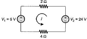
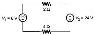
The power delivered by the two voltage sources of 6 V and 24 V as shown below will be
Detailed Solution for Test: AC Power Analysis- 2 - Question 4

Since V1 < V2, therefore the current wil! flow from V2 to V1 as shown below.


Hence, the whole power in the circuit will be supplied by V2 only. Total power delivered by the voltage source V2 is
PT = I2 x (2 + 4) + 6I
= 3x 6 + 6 x 3 = 54 + 18
= 72 watts

Test: AC Power Analysis- 2 - Question 5

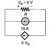
The power loss in watts in the resistor R shown below is
Detailed Solution for Test: AC Power Analysis- 2 - Question 5

VR = (10 + 5 VR) x R
Given, VR = 5 V
So, 5 = (10 + 5 x 5) R
or, 

∴ Power loss in R is

Test: AC Power Analysis- 2 - Question 6

The root mean square value of the current wave given by i = (50 + 30 sin t) A will be

Detailed Solution for Test: AC Power Analysis- 2 - Question 6


= 54.30 A

Test: AC Power Analysis- 2 - Question 7

Assertion (A): In an alternating circuit, if the current is (4 - j3) amperes and the impressed voltage is (100 - j50) volts, the reactive power in the circuit is 100 VA.
Reason (R): True power is the real part of (VI).

Detailed Solution for Test: AC Power Analysis- 2 - Question 7

V = (100 - j50) volt,
I = (4 - j3) A
∴ S = VI* = (100 - j50)(4 - j3)*
= (100 - j50)(4 + j3)
= 550 + j100
∴ P = 100 W and Q = 100 VAR
Q is in VAR not in VA. Hence, assertion is not correct.
Also P is the real part of apparent power (S = VI).

Test: AC Power Analysis- 2 - Question 8

In a purely resistive circuit, the average power
Pav is______the peak power Pmax.

Detailed Solution for Test: AC Power Analysis- 2 - Question 8

Instantaneous power in a purely resistive circuit is

Test: AC Power Analysis- 2 - Question 9

The power consumed in an inductive circuit will be

Detailed Solution for Test: AC Power Analysis- 2 - Question 9

In a purely inductive circuit, power consumed = Q = VI sin φ. In inductive circuit (having both R and L) power is consumed by resistor R which is P = VI cos φ.

Test: AC Power Analysis- 2 - Question 10

 A series circuit containing passive elements has the following current and applied voltage:​

The circuit elements

Detailed Solution for Test: AC Power Analysis- 2 - Question 10

Phase difference between v and i is

∴ power factor = cos φ = cos 75° lag
Since, i lags v therefore, the circuit elements may be resistance and inductance (Z = R + jXL) or it may be resistance, inductance and capacitance Z = R + j(XL - XC), so that p.f. becomes lagging.

25 docs|247 tests
Information about Test: AC Power Analysis- 2 Page
In this test you can find the Exam questions for Test: AC Power Analysis- 2 solved & explained in the simplest way possible. Besides giving Questions and answers for Test: AC Power Analysis- 2, EduRev gives you an ample number of Online tests for practice
Download as PDF