Electrical Engineering (EE) Exam  >  Electrical Engineering (EE) Tests  >  GATE Electrical Engineering (EE) Mock Test Series 2025  >  Test: Inverters- 2 - Electrical Engineering (EE) MCQ

Test: Inverters- 2 - Electrical Engineering (EE) MCQ


Test Description

10 Questions MCQ Test GATE Electrical Engineering (EE) Mock Test Series 2025 - Test: Inverters- 2

Test: Inverters- 2 for Electrical Engineering (EE) 2025 is part of GATE Electrical Engineering (EE) Mock Test Series 2025 preparation. The Test: Inverters- 2 questions and answers have been prepared according to the Electrical Engineering (EE) exam syllabus.The Test: Inverters- 2 MCQs are made for Electrical Engineering (EE) 2025 Exam. Find important definitions, questions, notes, meanings, examples, exercises, MCQs and online tests for Test: Inverters- 2 below.
Solutions of Test: Inverters- 2 questions in English are available as part of our GATE Electrical Engineering (EE) Mock Test Series 2025 for Electrical Engineering (EE) & Test: Inverters- 2 solutions in Hindi for GATE Electrical Engineering (EE) Mock Test Series 2025 course. Download more important topics, notes, lectures and mock test series for Electrical Engineering (EE) Exam by signing up for free. Attempt Test: Inverters- 2 | 10 questions in 45 minutes | Mock test for Electrical Engineering (EE) preparation | Free important questions MCQ to study GATE Electrical Engineering (EE) Mock Test Series 2025 for Electrical Engineering (EE) Exam | Download free PDF with solutions
Test: Inverters- 2 - Question 1

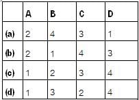
Match List-I (Type of Inverter circuits) with List-II (Applications/Limitations) and select the correct answer using the codes given below the lists:
List-I
A. Adjustable voltage inverter
B. Pulse width modulated inverter
C. Current source inverter
D. Voltage source inverter
List-II
1. Limited speed range of motor
2. Capable of regeneration
3. Good input power factor at al! frequencies
4. Possibility of short circuit across the source
Codes:
Detailed Solution for Test: Inverters- 2 - Question 1

• By using adjustable voltage inverter, speed range of motor is limited because of motor cogging at 6 Hz and below.
• In pulse width modulated inverter, input p.f. is good at all frequencies.
• A CSI has the capability of regeneration back to the a.c. line because d.c. link polarity can be reversed.
• In VSI, the misfiring of switching devices may cause short circuit across the source and create serious problems.

Test: Inverters- 2 - Question 2

A 200 V DC voltage is supplying power to an RCL load through a single-phase full bridge through a
R = 10 Ω, L = 60 mH, C = 100 μF.
If the output frequency is 50 Hz, The maximum thyristor current is

Detailed Solution for Test: Inverters- 2 - Question 2

Output voltage 
= 254.65 sin314t + 84.88 sin 942t + 50.93 sin 1570t
It is of the general form
V0 = V1 sin w1 t + V2 sin w2 t + V3 sin w3 t

Test: Inverters- 2 - Question 3

A single phase IGBT bridge inverter, compared to a single pulse PWM control, multiple pulse PWM

Detailed Solution for Test: Inverters- 2 - Question 3

In case of singte-putse width modulation (PWM), the width of the pulse is adjusted to reduce the harmonic. However, a single phase IGBT bridge inverter produces a square wave. This square wave contains  harmonic, harmonic andharmonic.

Test: Inverters- 2 - Question 4

In a single-pulse modulation of PWM inverters if pulse width is 120° then

Detailed Solution for Test: Inverters- 2 - Question 4

The rms value of amplitude of harmonic voltage of a single, pulse modulated wave is given by

(where, p = width of pulse an Vdc = supply dc voltage)
If the 3rd harmonic Is to be eliminated, then
EL3 = 0
i.e. 
or, 
or, 
= Required pulse width

Test: Inverters- 2 - Question 5

A single phase inverter as shown in figure below
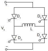
Which of the current wave form is true

Detailed Solution for Test: Inverters- 2 - Question 5

The output voltage wave form

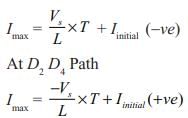
at D1 D3 Path


Test: Inverters- 2 - Question 6

A single-phase full bridge inverter can operate in load-commutation mode in case load consists of

Detailed Solution for Test: Inverters- 2 - Question 6

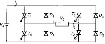
In a 1-φ full bridge inverter if RLC load is underdamped, then the two thyristors (namely T1 and T2) shown in figure will get commutated naturally and therefore no commutation circuitry will be needed. Thus, load commutation will be possible.

Test: Inverters- 2 - Question 7

An inverter has a periodic output voltage with the output waveform as shown in figure.
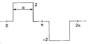
When the conduction angle a = 120°, the rms value of the output voltage is

Detailed Solution for Test: Inverters- 2 - Question 7


(Here, 2 pulse width = 120°)
∴ 

Test: Inverters- 2 - Question 8

Assertion (A): The terminal voltage of a voltage source inverter remains substantially constant with variations in load.
Reason (R): Any short-circuit across the terminals of a voltage source inverter causes current to rise very fast.

Detailed Solution for Test: Inverters- 2 - Question 8

A voltage source inverter is one in which the d.c. source has small or negligible impedance. Due to low internal impedance, the terminal voltage of a VSI remains substantially constant with variations in load. Reason is also a correct -statement because due to low time constant of internal impedance any short-circuit across the terminals of a VSI causes current to rise very fast. Hence, both assertion and reason are true but reason is not the correct explanation of assertion.

Test: Inverters- 2 - Question 9

A thyristor controlled induction motor working at a slip of 0.02 fed from voltage controlled source inverter as shown
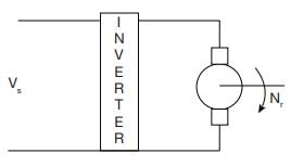
Operated at 50 Hz, 6 pole machine. The speed of rotor will be

Detailed Solution for Test: Inverters- 2 - Question 9

The machine operated at 50 Hz.

Synchronous speed Ns

A slip of S = 0.02
Nr = (1 - S) Ns = 980 rpm.

Test: Inverters- 2 - Question 10

A three phase 120 degree mode voltage source inverter connected to a resistive inductive load, R = 10 W, L = 200 mH. What will be the load power if inverter source voltage is 100 V dc.

Detailed Solution for Test: Inverters- 2 - Question 10

The average voltage across the inductor for a complete cycle is zero and also the power dissipated across
inductor per cycle is zero So,
The load power only due to resistor 


for 3 phases = 166.62 × 3 ≌ 500 Watt.

25 docs|247 tests
Information about Test: Inverters- 2 Page
In this test you can find the Exam questions for Test: Inverters- 2 solved & explained in the simplest way possible. Besides giving Questions and answers for Test: Inverters- 2, EduRev gives you an ample number of Online tests for practice
Download as PDF