Electrical Engineering (EE) Exam  >  Electrical Engineering (EE) Tests  >  GATE Electrical Engineering (EE) Mock Test Series 2025  >  Test: Measurement of Resistance to Electrical & Electronics Measurements - Electrical Engineering (EE) MCQ

Test: Measurement of Resistance to Electrical & Electronics Measurements - Electrical Engineering (EE) MCQ


Test Description

10 Questions MCQ Test GATE Electrical Engineering (EE) Mock Test Series 2025 - Test: Measurement of Resistance to Electrical & Electronics Measurements

Test: Measurement of Resistance to Electrical & Electronics Measurements for Electrical Engineering (EE) 2025 is part of GATE Electrical Engineering (EE) Mock Test Series 2025 preparation. The Test: Measurement of Resistance to Electrical & Electronics Measurements questions and answers have been prepared according to the Electrical Engineering (EE) exam syllabus.The Test: Measurement of Resistance to Electrical & Electronics Measurements MCQs are made for Electrical Engineering (EE) 2025 Exam. Find important definitions, questions, notes, meanings, examples, exercises, MCQs and online tests for Test: Measurement of Resistance to Electrical & Electronics Measurements below.
Solutions of Test: Measurement of Resistance to Electrical & Electronics Measurements questions in English are available as part of our GATE Electrical Engineering (EE) Mock Test Series 2025 for Electrical Engineering (EE) & Test: Measurement of Resistance to Electrical & Electronics Measurements solutions in Hindi for GATE Electrical Engineering (EE) Mock Test Series 2025 course. Download more important topics, notes, lectures and mock test series for Electrical Engineering (EE) Exam by signing up for free. Attempt Test: Measurement of Resistance to Electrical & Electronics Measurements | 10 questions in 30 minutes | Mock test for Electrical Engineering (EE) preparation | Free important questions MCQ to study GATE Electrical Engineering (EE) Mock Test Series 2025 for Electrical Engineering (EE) Exam | Download free PDF with solutions
Test: Measurement of Resistance to Electrical & Electronics Measurements - Question 1

In order to reduce skin effect in resistance standards when they are used on high frequency a.c.

Detailed Solution for Test: Measurement of Resistance to Electrical & Electronics Measurements - Question 1
  • To reduce the error in standard resistance due to stray inductance, the adjacent wires should carry current in opposite direction so as to reduce the resultant magnetic field.
  • To reduce the error due to contact (lead) resistance, a four terminal construction is used.
  • To reduce the skin effect when used at high frequency a.c., small diameter wires are used.
Test: Measurement of Resistance to Electrical & Electronics Measurements - Question 2

The condition for a resistor to have the same value of resistance at medium frequencies as with d.c. is

Detailed Solution for Test: Measurement of Resistance to Electrical & Electronics Measurements - Question 2

At high and medium frequencies, a resistor can be represented as shown in figure below.

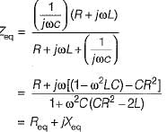
The equivalent impedance of the above shown resistor at an angular frequency ω rad/s is 


If the resistance is to remain independent of frequency i.e. to have the same value of resistance at medium frequencies as with d.c, we have:
CR2 = 2 L
so that, Req = R

Test: Measurement of Resistance to Electrical & Electronics Measurements - Question 3

A resistor R has an effective inductance of L and a distributed capacitance of C. its time constant at medium frequencies is

Detailed Solution for Test: Measurement of Resistance to Electrical & Electronics Measurements - Question 3

At medium frequencies, we have:

∴ Time constant,

Test: Measurement of Resistance to Electrical & Electronics Measurements - Question 4

A 100 Ω resistor has a time constant of 30 ns. What is the value of capacitor to be connected in parallel with the resistor to make its phase angle equal to zero?

Detailed Solution for Test: Measurement of Resistance to Electrical & Electronics Measurements - Question 4

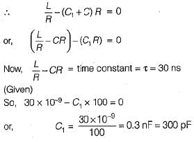
Let the the required capacitance be C1.

Without the external capacitance C1,

Now, when an external capacitance C1 is connected in parallel, then new phase angle

For the phase angle to be zero, tan φ = 0

Test: Measurement of Resistance to Electrical & Electronics Measurements - Question 5

Assertion (A): Manganin is an alloy of copper, manganese and nickel and is universally used as resistance material for precision resistors and for resistance measuring apparatus,
Reason (R): The foremost property of manganin is that it has almost zero temperature coefficient of resistance near about room temperature. Moreover, it shows no ageing effect.

Test: Measurement of Resistance to Electrical & Electronics Measurements - Question 6

A resistance R is measured using the connections shown in figure below.

The current measured is 10 A on a range 10 A and the voltage measured is 125 V on a range of 150 V. The scale of the ammeter and voltmeter are uniform, the total scale divisions of ammeter are 100 and that of voltmeter are 150. The scales of these instruments are such that 1/10 of a scale can be distinguished. The constructional error of the ammeter is ±0.3% and that of voltmeter is ±0.4%. The resistance of ammeter is 0.25 Ω. The unknown resistance will be specified as:

Detailed Solution for Test: Measurement of Resistance to Electrical & Electronics Measurements - Question 6

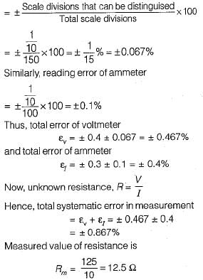
Reading error of voltmeter

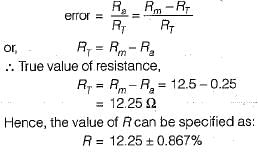
For the arrangement shown in given figure, ammeter is near to the unknown test resistance (R), therefore

Test: Measurement of Resistance to Electrical & Electronics Measurements - Question 7

Each of the ratio arms of a laboratory type Wheatstone bridge has guaranteed accuracy of ±0.05%, while the standard arm has a guaranteed accuracy of ±0.1 %. The ratio arms are both set at 1 kΩ and and bridge is balanced with standard arm adjusted to 3154 Ω. The upper and the lower limits of the unknown resistance, based upon the guaranteed accuracies of the known bridge arms are respectively

Detailed Solution for Test: Measurement of Resistance to Electrical & Electronics Measurements - Question 7

Value of unknown resistance, 

Now, percentage error in determination of R is

Test: Measurement of Resistance to Electrical & Electronics Measurements - Question 8

A highly sensitive galvanometer can detect a current as low as 0.1 nA. This galvanometer is used in a Wheatstone bridge as a detector as shown in figure below. The resistance of galvanometer is negligible.
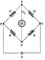
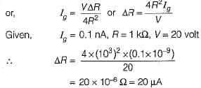
Each arm of the bridge has a resistance of 1 kΩ and the input voltage applied to bridge is 20 V. Neglecting the resistance of the galvanometer as compared with the internal resistance of bridge, the smallest change in the resistance which can be detected is

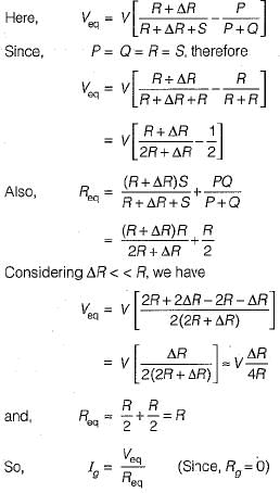
Detailed Solution for Test: Measurement of Resistance to Electrical & Electronics Measurements - Question 8

Let the resistance R be changed to R + ΔR.
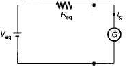
The Thevenin's equivalent circuit across terminals bd is shown below.


Test: Measurement of Resistance to Electrical & Electronics Measurements - Question 9

A cable is tested by loss of charge method using a ballistic galvanometer with following results:
Discharged immediately after electrification, deflection 200 divisions.
Discharged after 20s and after electrification:
(i) deflection, 100 divisions,
(ii) when in parallel with a resistance of 10 MW, deflection 50 divisions.
What is the insulation resistance of the cable? 

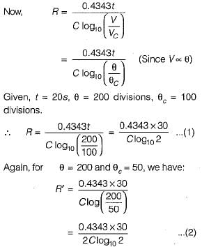
Detailed Solution for Test: Measurement of Resistance to Electrical & Electronics Measurements - Question 9

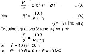
Let R be the insulation resistance of the cable and R' be the equivalent resistance of the parallel combination of insulation resistance R and 10 MΩ resistance.

Dividing equation (1) by (2), we get: 

Test: Measurement of Resistance to Electrical & Electronics Measurements - Question 10

Consider the following statements about the bridge measurement:
1. The measurement accuracy is directly related to the accuracy of the bridge component as well as that of the null indicator used.
2. The basic dc bridge used for accurate measurement of resistance is called Wheatstone’s bridge.
3. When the bridge is in balanced condition, current flows through the galvanometer, causing a deflection of its pointer.
4. A more sensitive galvanometer deflects by a greater amount for the same current.
5. The sensitivity of the bridge measurement can only be expressed in mm/μA.
Which of these statements is/are correct?

Detailed Solution for Test: Measurement of Resistance to Electrical & Electronics Measurements - Question 10
  • The measurement accuracy is directly related to the accuracy of the bridge component and not to that of the null indicator used.
  • When the bridge is in balanced condition, no current flows through the galvanometer.
  • The sensitivity of the bridge measurement can be expressed in mm/μA or degree/mA or radians/mA.
25 docs|247 tests
Information about Test: Measurement of Resistance to Electrical & Electronics Measurements Page
In this test you can find the Exam questions for Test: Measurement of Resistance to Electrical & Electronics Measurements solved & explained in the simplest way possible. Besides giving Questions and answers for Test: Measurement of Resistance to Electrical & Electronics Measurements, EduRev gives you an ample number of Online tests for practice
Download as PDF