Electronics and Communication Engineering (ECE) Exam  >  Electronics and Communication Engineering (ECE) Tests  >  GATE ECE (Electronics) Mock Test Series 2025  >  Test: Frequency Domain Analysis of Control Systems - 1 - Electronics and Communication Engineering (ECE) MCQ

Test: Frequency Domain Analysis of Control Systems - 1 - Electronics and Communication Engineering (ECE) MCQ


Test Description

10 Questions MCQ Test GATE ECE (Electronics) Mock Test Series 2025 - Test: Frequency Domain Analysis of Control Systems - 1

Test: Frequency Domain Analysis of Control Systems - 1 for Electronics and Communication Engineering (ECE) 2025 is part of GATE ECE (Electronics) Mock Test Series 2025 preparation. The Test: Frequency Domain Analysis of Control Systems - 1 questions and answers have been prepared according to the Electronics and Communication Engineering (ECE) exam syllabus.The Test: Frequency Domain Analysis of Control Systems - 1 MCQs are made for Electronics and Communication Engineering (ECE) 2025 Exam. Find important definitions, questions, notes, meanings, examples, exercises, MCQs and online tests for Test: Frequency Domain Analysis of Control Systems - 1 below.
Solutions of Test: Frequency Domain Analysis of Control Systems - 1 questions in English are available as part of our GATE ECE (Electronics) Mock Test Series 2025 for Electronics and Communication Engineering (ECE) & Test: Frequency Domain Analysis of Control Systems - 1 solutions in Hindi for GATE ECE (Electronics) Mock Test Series 2025 course. Download more important topics, notes, lectures and mock test series for Electronics and Communication Engineering (ECE) Exam by signing up for free. Attempt Test: Frequency Domain Analysis of Control Systems - 1 | 10 questions in 30 minutes | Mock test for Electronics and Communication Engineering (ECE) preparation | Free important questions MCQ to study GATE ECE (Electronics) Mock Test Series 2025 for Electronics and Communication Engineering (ECE) Exam | Download free PDF with solutions
Test: Frequency Domain Analysis of Control Systems - 1 - Question 1

The Bode diagram approach is the most commonly used method for the analysis and synthesis of

Detailed Solution for Test: Frequency Domain Analysis of Control Systems - 1 - Question 1

- The Bode diagram is used in control systems to analyze the frequency response of linear time-invariant systems.
- It is particularly useful for linear feedback control systems because it helps in assessing system stability and performance.
- Bode plots illustrate how the gain and phase of a system vary with frequency, aiding in the design and tuning of controllers.
- Non-linear systems are not typically analyzed using Bode plots due to their complex, non-linear behavior.
- Therefore, the correct answer is D: linear feedback control system only.

Test: Frequency Domain Analysis of Control Systems - 1 - Question 2

Nichol's chart is a plot of

Test: Frequency Domain Analysis of Control Systems - 1 - Question 3

The initial slope of Bode plot for a transfer function having no poles at origin is

Detailed Solution for Test: Frequency Domain Analysis of Control Systems - 1 - Question 3

With no-pole at origin, initial slope will be OdB/decade.
For n-pole at origin, initial slope will be -20 ndB/decade.

Test: Frequency Domain Analysis of Control Systems - 1 - Question 4

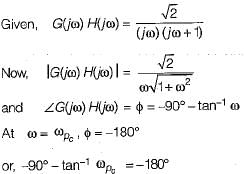
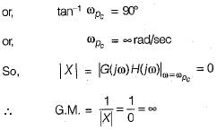
The gain margin of a control system having the loop transfer function G(s)H(s) = 

Detailed Solution for Test: Frequency Domain Analysis of Control Systems - 1 - Question 4


Test: Frequency Domain Analysis of Control Systems - 1 - Question 5

Gain crossover frequency is the frequency at which the gain of G(jω) is

Detailed Solution for Test: Frequency Domain Analysis of Control Systems - 1 - Question 5

Test: Frequency Domain Analysis of Control Systems - 1 - Question 6

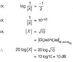
For a control system having gain margin of -10 dB, the magnitude of GH(s) for 180° phase shift is

Detailed Solution for Test: Frequency Domain Analysis of Control Systems - 1 - Question 6


Test: Frequency Domain Analysis of Control Systems - 1 - Question 7

A system with phase margin close to zero or gain margin close to unity is 

Test: Frequency Domain Analysis of Control Systems - 1 - Question 8

If the transfer function of a first-order system in  then the time constant of this system will be

Detailed Solution for Test: Frequency Domain Analysis of Control Systems - 1 - Question 8


Hence, time constant = T= 5 seconds

Test: Frequency Domain Analysis of Control Systems - 1 - Question 9

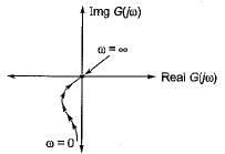
The polar plot of  

Detailed Solution for Test: Frequency Domain Analysis of Control Systems - 1 - Question 9


Given system is of type-1 and order-2, therefore its polar plot will be as shown below.

Hence, the polar plot will neither cross the real axis nor the imaginary axis.

Test: Frequency Domain Analysis of Control Systems - 1 - Question 10

The magnitude of frequency response of an under-sampled second order system is 5 at 0 rad/sec and peaks to 10/√3 at 5√2 rad/sec. The transfer function of the system is

Detailed Solution for Test: Frequency Domain Analysis of Control Systems - 1 - Question 10

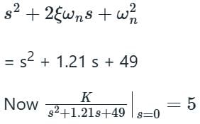
DC gain = 5

100 [4ε2 (1 – ε2)] = 3
400 ε2 – 400 ε4 = 3
400 x2 – 400 x + 3 = 0  
x2 – x + 0.0075 = 0
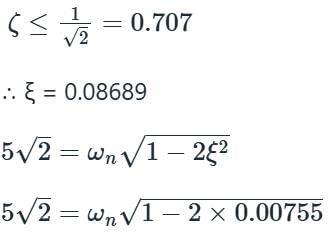
ξ2 = 0.99244 , ξ2 = 0.00755
ξ = 0.99 , ξ = 0.08689
If resonant peak > 1 then

ωn = 7 rad/s

K = 49 × 5 = 245

25 docs|263 tests
Information about Test: Frequency Domain Analysis of Control Systems - 1 Page
In this test you can find the Exam questions for Test: Frequency Domain Analysis of Control Systems - 1 solved & explained in the simplest way possible. Besides giving Questions and answers for Test: Frequency Domain Analysis of Control Systems - 1, EduRev gives you an ample number of Online tests for practice
Download as PDF