Electrical Engineering (EE) Exam  >  Electrical Engineering (EE) Tests  >  GATE Electrical Engineering (EE) Mock Test Series 2025  >  Test: Signal Flow Graphs - 1 - Electrical Engineering (EE) MCQ

Test: Signal Flow Graphs - 1 - Electrical Engineering (EE) MCQ


Test Description

15 Questions MCQ Test GATE Electrical Engineering (EE) Mock Test Series 2025 - Test: Signal Flow Graphs - 1

Test: Signal Flow Graphs - 1 for Electrical Engineering (EE) 2024 is part of GATE Electrical Engineering (EE) Mock Test Series 2025 preparation. The Test: Signal Flow Graphs - 1 questions and answers have been prepared according to the Electrical Engineering (EE) exam syllabus.The Test: Signal Flow Graphs - 1 MCQs are made for Electrical Engineering (EE) 2024 Exam. Find important definitions, questions, notes, meanings, examples, exercises, MCQs and online tests for Test: Signal Flow Graphs - 1 below.
Solutions of Test: Signal Flow Graphs - 1 questions in English are available as part of our GATE Electrical Engineering (EE) Mock Test Series 2025 for Electrical Engineering (EE) & Test: Signal Flow Graphs - 1 solutions in Hindi for GATE Electrical Engineering (EE) Mock Test Series 2025 course. Download more important topics, notes, lectures and mock test series for Electrical Engineering (EE) Exam by signing up for free. Attempt Test: Signal Flow Graphs - 1 | 15 questions in 10 minutes | Mock test for Electrical Engineering (EE) preparation | Free important questions MCQ to study GATE Electrical Engineering (EE) Mock Test Series 2025 for Electrical Engineering (EE) Exam | Download free PDF with solutions
Test: Signal Flow Graphs - 1 - Question 1

A signal flow graph is the graphical representation of the relationships between the variables of set linear algebraic equations.

Detailed Solution for Test: Signal Flow Graphs - 1 - Question 1

Explanation: By definition signal flow graphs are the graphical representation of the relationships between the variables of set linear algebraic equations.

Test: Signal Flow Graphs - 1 - Question 2

A node having only outgoing branches.

Detailed Solution for Test: Signal Flow Graphs - 1 - Question 2

Explanation: Nodes are the point by which the branches are outgoing or ingoing and this can be input or output node and input node is the node having only outgoing branches.

1 Crore+ students have signed up on EduRev. Have you? Download the App
Test: Signal Flow Graphs - 1 - Question 3

Use mason’s gain formula to find the transfer function of the given signal flow graph:

Detailed Solution for Test: Signal Flow Graphs - 1 - Question 3

Explanation: Using mason’s gain formula transfer function from signal flow graph can be calculated which relates the forward path gain to the various paths and loops.

Test: Signal Flow Graphs - 1 - Question 4

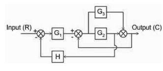
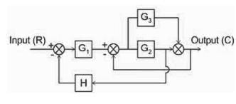
What will be the transfer function of the given block diagram?
Detailed Solution for Test: Signal Flow Graphs - 1 - Question 4


Forward path: G1 G2, G1 G3

Loops: -G2, -G1G2H, -G3

Finding the transfer function using Mason's gain formula:

Test: Signal Flow Graphs - 1 - Question 5

Signal flow graphs:

Detailed Solution for Test: Signal Flow Graphs - 1 - Question 5

Explanation: Signal flow graphs are used to find the transfer function of control system by converting the block diagrams into signal flow graphs or directly but cannot be used for nonlinear systems.

Test: Signal Flow Graphs - 1 - Question 6

Signal flow graphs are reliable to find transfer function than block diagram reduction technique.

Detailed Solution for Test: Signal Flow Graphs - 1 - Question 6

Explanation: As one set technique and formula is used here but in block diagram technique various methods are involved which increases complexity.

Test: Signal Flow Graphs - 1 - Question 7

Loop which do not possess any common node are said to be ___________ loops.

Detailed Solution for Test: Signal Flow Graphs - 1 - Question 7

Explanation: Loop is the part of the network in which the branch starts from the node and comes back to the same node and non touching loop must not have any node in common.

Test: Signal Flow Graphs - 1 - Question 8

The relationship between an input and output variable of a signal flow graph is given by the net gain between the input and output node is known as the overall______________

Detailed Solution for Test: Signal Flow Graphs - 1 - Question 8

Explanation: The relationship between input and output variable of a signal flow graph is the overall gain of the system.

Test: Signal Flow Graphs - 1 - Question 9

Use mason’s gain formula to calculate the transfer function of given figure:

Detailed Solution for Test: Signal Flow Graphs - 1 - Question 9

Explanation: Use mason’s gain formula to solve the signal flow graph and by using mason’s gain formula transfer function from signal flow graph can be calculated which relates the forward path gain to the various paths and loops.

Test: Signal Flow Graphs - 1 - Question 10

Use mason’s gain formula to find the transfer function of the given figure:
  

Detailed Solution for Test: Signal Flow Graphs - 1 - Question 10

Explanation: Using mason’s gain formula transfer function from signal flow graph can be calculated which relates the forward path gain to the various paths and loops.

Test: Signal Flow Graphs - 1 - Question 11

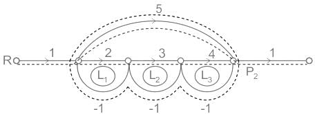
In the signal flow graph of figure given below, the gain C/R will be

Detailed Solution for Test: Signal Flow Graphs - 1 - Question 11

Concept:

Mason’s Gain Formula

  • It is a technique used for finding the transfer function of a control system. A formula that determines the transfer function of a linear system by making use of the signal flow graph is known as Mason’s Gain Formula.
  • It shows its significance in determining the relationship between input and output.

Suppose there are ‘N’ forward paths in a signal flow graph. The gain between the input and the output nodes of a signal flow graph is nothing but the transfer function of the system. It can be calculated by using Mason’s gain formula.

Mason’s gain formula is

Where,

C(s) is the output node

R(s) is the input node

T is the transfer function or gain between R(s) and C(s)

Pi is the ith forward path gain

Δ = 1−(sum of all individual loop gains) + (sum of gain products of all possible two non-touching loops) − (sum of gain products of all possible three non-touching loops) + ........

Δi is obtained from Δ by removing the loops which are touching the ith forward path.

Calculations:

The forward paths are as follows:

P1 = 5

P2 = 2 × 3 × 4 = 24

The loops are as follows:

L1 = -2, L2 = -3, L3 = -4, L4 = -5

The two non-touching loops are:

L1L3 = 8

There is no three non-touching loops

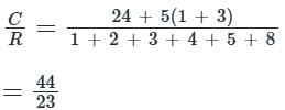
By Mason’s gain formula:-

Test: Signal Flow Graphs - 1 - Question 12

The signal flow graph for a system is given below.
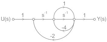
The transfer function Y(s)/U(s) for this system is 

Detailed Solution for Test: Signal Flow Graphs - 1 - Question 12

Concept:

Signal flow graph

  • It is a graphical representation of a set of linear algebraic equations between input and output.
  • The set of linear algebraic equations represents the systems.
  • The signal flow graphs are developed to avoid mathematical calculation.

Maon gain formula is used to find the ratio of any two nodes or transfer function.

Where Pk = kth forward path gain

Δ = 1- ∑ individual loop gain + ∑ two non-touching loops gain - ∑ the gain product of three non-touching loops + ∑ gain of four non-touching loops

Shotcut: while writing Δ take the opposite sign for the odd number of non-touching loops snd the same sign for the even the number of non-touching loops.

ΔK is obtained from Δ by removing the loops touching the Kth forward path.

Calculation:

For the given SFG two forward paths

Since all loops are touching the paths PK1 and PK2 so ΔK1 = ΔK2 = 1
We have Δ = 1- ∑ individual loops + ∑ non-touching loops gain
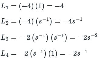
Loops are

As all the loops are touching each other we have
Δ = 1 – ( L1 + L2 + L3 + L4)
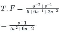
Δ = 1 – ( - 4 – 4s-1 – 2s-2 -2s-1 )
Δ = 5 + 6s-1 + 2s-2 

Test: Signal Flow Graphs - 1 - Question 13

A node having only outgoing branches.

Detailed Solution for Test: Signal Flow Graphs - 1 - Question 13

Nodes are the point by which the branches are outgoing or ingoing and this can be input or output node and input node is the node having only outgoing branches.

Test: Signal Flow Graphs - 1 - Question 14

Signal flow graph is a 

Detailed Solution for Test: Signal Flow Graphs - 1 - Question 14

Concept:

  • A signal flow graph is a graphical representation of a set of linear algebraic or differential equations. It is a diagram that represents a set of simultaneous linear equations using nodes and directed branches. In control system engineering, signal flow graphs are used to quickly solve the equations related to systems.
  • Each node represents a system variable, and each directed branch represents a gain or a multiplication factor between two variables. The direction of the arrow represents the direction of the flow of the signal. The summing and branching points are used to represent system equations in a graphical way.
  • Although signal flow graphs are used in the analysis of control systems (option 4), it's not a special type of graph solely for modern control systems. They can be used for a variety of applications involving sets of linear equations, not just modern control systems.

Node:

  • A node that has only outgoing branches called input mode
  • Which has only incoming branches, known as an output node
  • Which has both incoming & outgoing branches, mixed node.             

Branch:

  • It is an alone segment that joins two nodes.
  • It has both gain & direction
Test: Signal Flow Graphs - 1 - Question 15

Which of the options is an equivalent representation of the signal flow graph shown here?
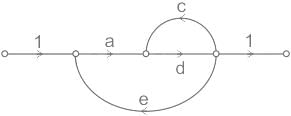
Detailed Solution for Test: Signal Flow Graphs - 1 - Question 15

Concept:

According to Mason’s gain formula, the transfer function is given by

Where, n = no of forward paths

Mk = kth forward path gain

Δk = the value of Δ which is not touching the kth forward path

Δ = 1 – (sum of the loop gains) + (sum of the gain product of two non-touching loops) – (sum of the gain product of three non-touching loops)

Application:

In the given signal flow graph,

Forward paths: P1 = ad

Loops: L1 = cd, L2 = ade

Δ = 1 – (cd + ade)

Δ1 = 1

Transfer function = 
Now, let us check the options.

Option 1:

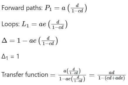
Forward paths: P1 = a(d + c)

Loops: L1 = ae(d + c)

Δ = 1 – ae(d + c)

Δ1 = 1

Transfer function = 

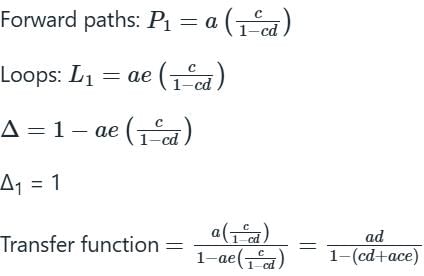
Option 2:

Forward paths: P1 = d(a + c)

Loops: L1 = de(a + c)

Δ = 1 – de(a + c)

Δ1 = 1

Transfer function = 

Option 3:

Option 4:

Hence the signal graph in option (C) is the equivalent representation of the signal flow graph given in the question.

25 docs|247 tests
Information about Test: Signal Flow Graphs - 1 Page
In this test you can find the Exam questions for Test: Signal Flow Graphs - 1 solved & explained in the simplest way possible. Besides giving Questions and answers for Test: Signal Flow Graphs - 1, EduRev gives you an ample number of Online tests for practice

Top Courses for Electrical Engineering (EE)

Download as PDF

Top Courses for Electrical Engineering (EE)