Electrical Engineering (EE) Exam  >  Electrical Engineering (EE) Tests  >  GATE Electrical Engineering (EE) Mock Test Series 2025  >  Test: Basic Nodal & Mesh Analysis- 2 - Electrical Engineering (EE) MCQ

Test: Basic Nodal & Mesh Analysis- 2 - Electrical Engineering (EE) MCQ


Test Description

10 Questions MCQ Test GATE Electrical Engineering (EE) Mock Test Series 2025 - Test: Basic Nodal & Mesh Analysis- 2

Test: Basic Nodal & Mesh Analysis- 2 for Electrical Engineering (EE) 2025 is part of GATE Electrical Engineering (EE) Mock Test Series 2025 preparation. The Test: Basic Nodal & Mesh Analysis- 2 questions and answers have been prepared according to the Electrical Engineering (EE) exam syllabus.The Test: Basic Nodal & Mesh Analysis- 2 MCQs are made for Electrical Engineering (EE) 2025 Exam. Find important definitions, questions, notes, meanings, examples, exercises, MCQs and online tests for Test: Basic Nodal & Mesh Analysis- 2 below.
Solutions of Test: Basic Nodal & Mesh Analysis- 2 questions in English are available as part of our GATE Electrical Engineering (EE) Mock Test Series 2025 for Electrical Engineering (EE) & Test: Basic Nodal & Mesh Analysis- 2 solutions in Hindi for GATE Electrical Engineering (EE) Mock Test Series 2025 course. Download more important topics, notes, lectures and mock test series for Electrical Engineering (EE) Exam by signing up for free. Attempt Test: Basic Nodal & Mesh Analysis- 2 | 10 questions in 30 minutes | Mock test for Electrical Engineering (EE) preparation | Free important questions MCQ to study GATE Electrical Engineering (EE) Mock Test Series 2025 for Electrical Engineering (EE) Exam | Download free PDF with solutions
Test: Basic Nodal & Mesh Analysis- 2 - Question 1

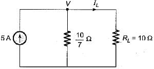
For the circuit shown below, the value of current through RL is
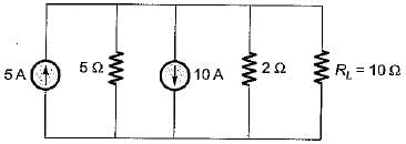
Detailed Solution for Test: Basic Nodal & Mesh Analysis- 2 - Question 1

The given circuit can be reduced by combining resistors and current sources as shown below.

Let the node voltage be V volts.
Applying nodal analysis, we have

or, 
or, 
or, 5 + 
or, 
or, 
So, 

Test: Basic Nodal & Mesh Analysis- 2 - Question 2

In nodal analysis, if there are N nodes in the circuit, then how many equations will be written to solve the network ?

Test: Basic Nodal & Mesh Analysis- 2 - Question 3

In the node voltage technique of solving networks, choice of a reference node does not
1. affect the operation of the circuit.​
2. change the voltage across any element.
3. affect the pd between any pair of nodes.
4. affect the voltages of various nodes.
Q. Which of the above statements is/are true?

Test: Basic Nodal & Mesh Analysis- 2 - Question 4

Nodal analysis is based on

Test: Basic Nodal & Mesh Analysis- 2 - Question 5

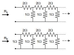
RA and RB are the input resistances of circuits as shown below. The circuits extend infinitely in the direction shown. Which one of the following statements is TRUE?
Detailed Solution for Test: Basic Nodal & Mesh Analysis- 2 - Question 5

If the equivalent resistance of first figure is RA then from the second figure, we can see that
RB=RA||1Ω.
RB= RA /(1+RA)

Test: Basic Nodal & Mesh Analysis- 2 - Question 6

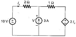
In the circuit shown below, the value of lx is
Detailed Solution for Test: Basic Nodal & Mesh Analysis- 2 - Question 6

Applying nodal analysis at the given node, we have

or, 3Ix = V - 3 ...(i)
Also, 10 = 2Ix + V
or, V = 10 - 2Ix ...(ii)
Putting V from equation (ii) into equation (i),
3I= 10 - 2Ix - 3
or, 5Ix = 7
or, 

Test: Basic Nodal & Mesh Analysis- 2 - Question 7

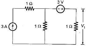
The value of V1 in the circuit shown in the given figure is​

Detailed Solution for Test: Basic Nodal & Mesh Analysis- 2 - Question 7

Let the node voltage be V' volts.
Applying nodal analysis at the given node, we have

or, 2V' = 0
or, V' = 0 volts
Now, V' = - 3 + 11
or, 0 = - 3 + V1
or, V1 = 3 volts

Test: Basic Nodal & Mesh Analysis- 2 - Question 8

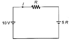
Consider the electrical network shown below.
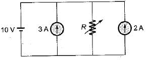
Determine the value of R such that current supplied by the voltage source is zero?

Detailed Solution for Test: Basic Nodal & Mesh Analysis- 2 - Question 8

The given circuit can be redrawn as shown below (By combining current sources).

Now, I = 0 (Given)
i.e. 
or, R = 2Ω

Test: Basic Nodal & Mesh Analysis- 2 - Question 9

Assertion (A): In the method of solution of the network using nodal analysis, the assumption is made that the node potential is always higher than the other voltages appearing in the equation.
Reason (R): Nodal analysis is used to find the branch currents.

Detailed Solution for Test: Basic Nodal & Mesh Analysis- 2 - Question 9

Node potential is always higher than the other voltages appearing in the equations otherwise a negative value for current would result.

Test: Basic Nodal & Mesh Analysis- 2 - Question 10

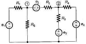
The nodal equations of the circuit shown below are respectively given by
 

Detailed Solution for Test: Basic Nodal & Mesh Analysis- 2 - Question 10

We have,


25 docs|247 tests
Information about Test: Basic Nodal & Mesh Analysis- 2 Page
In this test you can find the Exam questions for Test: Basic Nodal & Mesh Analysis- 2 solved & explained in the simplest way possible. Besides giving Questions and answers for Test: Basic Nodal & Mesh Analysis- 2, EduRev gives you an ample number of Online tests for practice
Download as PDF