Electrical Engineering (EE) Exam  >  Electrical Engineering (EE) Tests  >  Analog and Digital Electronics  >  Analog Electronics - 6 - Electrical Engineering (EE) MCQ

Analog Electronics - 6 - Electrical Engineering (EE) MCQ


Test Description

10 Questions MCQ Test Analog and Digital Electronics - Analog Electronics - 6

Analog Electronics - 6 for Electrical Engineering (EE) 2025 is part of Analog and Digital Electronics preparation. The Analog Electronics - 6 questions and answers have been prepared according to the Electrical Engineering (EE) exam syllabus.The Analog Electronics - 6 MCQs are made for Electrical Engineering (EE) 2025 Exam. Find important definitions, questions, notes, meanings, examples, exercises, MCQs and online tests for Analog Electronics - 6 below.
Solutions of Analog Electronics - 6 questions in English are available as part of our Analog and Digital Electronics for Electrical Engineering (EE) & Analog Electronics - 6 solutions in Hindi for Analog and Digital Electronics course. Download more important topics, notes, lectures and mock test series for Electrical Engineering (EE) Exam by signing up for free. Attempt Analog Electronics - 6 | 10 questions in 30 minutes | Mock test for Electrical Engineering (EE) preparation | Free important questions MCQ to study Analog and Digital Electronics for Electrical Engineering (EE) Exam | Download free PDF with solutions
Analog Electronics - 6 - Question 1

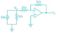
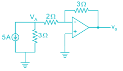
The current flowing through the 3 Ω resistor R1 is _____ A.
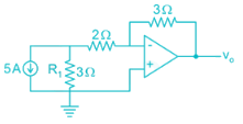
Detailed Solution for Analog Electronics - 6 - Question 1


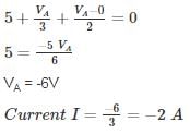
Apply nodal at A:

Magnitude wise: 2 A

*Answer can only contain numeric values
Analog Electronics - 6 - Question 2

An op-amp has a voltage gain of 100 dB at dc and a unity gain frequency of 5 MHz. The lower 3-dB cut off frequency is _______ Hz.


Detailed Solution for Analog Electronics - 6 - Question 2

100 dB voltage gain

20 log (Gain) = 100

Gain = 105

GBW = 5 MHz

Low frequency 3-dB = 
= 50 Hz.

*Answer can only contain numeric values
Analog Electronics - 6 - Question 3

An op-amp with slew rate 1 V/μ is used in the circuit below input step voltage Vi = V sin (105t) is given, the maximum value of V such that no raise time distortion occurs at the output is _____V.
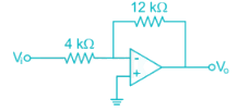

Detailed Solution for Analog Electronics - 6 - Question 3

The output Vo = -3V sin (ω0t)

For no distortion to occur

3Vω0 ≤ SR

*Answer can only contain numeric values
Analog Electronics - 6 - Question 4

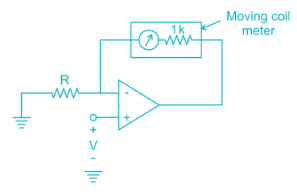
The circuit shows an analog voltmeter of very high input impedance that uses an inexpensive moving coil-meter. The voltmeter measures the voltage ‘V’ applied between the op-amp’s positive-input terminal and ground. Assuming that the moving coil produces full-scale deflection when the current passing through it is 100 μA, the value of R (in kΩ) to obtain full-scale reading at +10 V is

Detailed Solution for Analog Electronics - 6 - Question 4


VA = V (virtual ground)

Analog Electronics - 6 - Question 5

Circuit shows an op-amp circuit used for generating the square waveform.
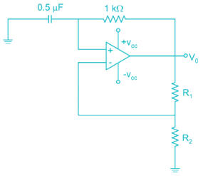
If the output frequency required in 1 kHz. then the possible values of R1­ and R2 can be respectively


Detailed Solution for Analog Electronics - 6 - Question 5

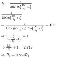
Frequency of oscillation


If R1 = 2k

R2 = 0.859 × 2

= 1.7 k

Option 1 is correct.

*Answer can only contain numeric values
Analog Electronics - 6 - Question 6

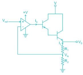
The circuit shows the series voltage regulator.
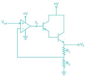
If reference voltage Vref is 2V and R1 = 3K, R2 = 1K, β = 99 for both transistors. Then the value of current I0 in micro-amperes is _____ μA.


Detailed Solution for Analog Electronics - 6 - Question 6

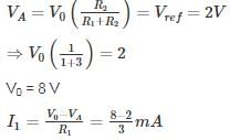
V- = V+ = 2V


= 2 mA

I1 = (1 + β) (1 + β) I0

2 mA = 104 I0

I = 0.2 uA

Analog Electronics - 6 - Question 7

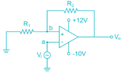
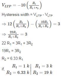
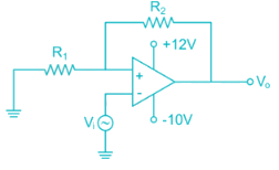
The circuit shows an – op-amp in Schmidt Trigger configuration. If the hysteresis width is 3V. Then the value of R1 and R2 is
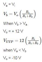
Detailed Solution for Analog Electronics - 6 - Question 7


*Answer can only contain numeric values
Analog Electronics - 6 - Question 8

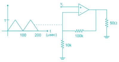
For the amplifier circuit shown, the op-amp can deliver a maximum current of 100 mA and is powered by ±15 V supply. If the input to the amplifier is a triangular waveform as shown. The peak value of the output waveform is ______.

Detailed Solution for Analog Electronics - 6 - Question 8

The circuit is non-inverting.

Amplifier:

= 11V

However the current flowing through load when V0 = 11 V is

Which is more than the current op-amp can supply.

Thus peak value is limited by the maximum current:

50 Ω ≪ 110 kΩ

All the current flows through 50 Ω resistor.

V0 = (100 mA) (50 Ω)

= 5 V

Analog Electronics - 6 - Question 9

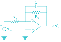
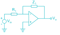
An op-amp circuit is shown in the figure. If Vin is an AC source of frequency ω.
Consider the following statements:
a) For ω Circuit is an integrator
(b) For ω circuit is an Amplifier

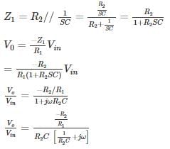
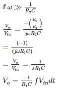
Detailed Solution for Analog Electronics - 6 - Question 9


Circuit acts like an Integrator

Circuit acts an Inverting Amplifier

The given conditions in question is opposite Hence None of a and b is correct

*Answer can only contain numeric values
Analog Electronics - 6 - Question 10

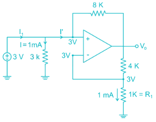
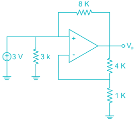
The average power delivered by the 3 V source is ________ mW.

Detailed Solution for Analog Electronics - 6 - Question 10


V- = V+ = 3 V [Virtual ground]

Current through 1 k resistor

I = 1 mA

Voltage across 1k resistor from voltage division

Voltage across  


Vo = 15 V

KVL at V+ node:

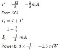
3 – I'(8) = Vo

3 – I'(8) = 15

3 – 15 = I'(8)

137 videos|144 docs|71 tests
Information about Analog Electronics - 6 Page
In this test you can find the Exam questions for Analog Electronics - 6 solved & explained in the simplest way possible. Besides giving Questions and answers for Analog Electronics - 6, EduRev gives you an ample number of Online tests for practice
137 videos|144 docs|71 tests
Download as PDF