Analog Electronics - 4 - Electrical Engineering (EE) MCQ
10 Questions MCQ Test Analog and Digital Electronics - Analog Electronics - 4

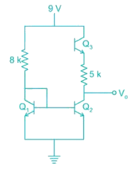
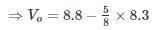
In the circuit shown below all the transistors are identical with; VBE = 0.7 V; VCE(sat) = 0.2 If the transistor Q3 is in saturation then V0 is


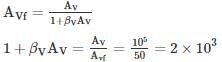
Consider series-shunt amplifier in which the open loop gain is Av = 105 and the closed loop gain is AVf = 50. Assume the input and output resistance of the basic amplifier are Ri = 10 kΩ and Ro = 20 kΩ. Determine the input resistance of series input connecting and the output resistance of a shunt output connection for an ideal feedback voltage amplifier.
 The output resistance is
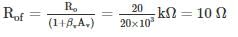
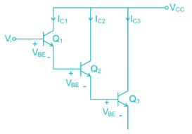
For the circuit shown in fig, the transconductance of Q1 is gm1, of Q2 is gm2 and Q3 is gm3 then the overall trans-conductance gm is
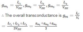
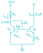
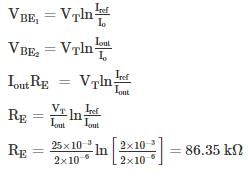
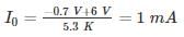
The circuit shown in figure uses matched transistor. With a thermal voltage VT = 25 mV, The value of β is very high. Find the value of emitter resistance in kΩ
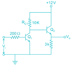
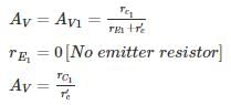
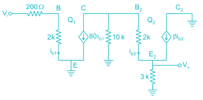
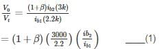
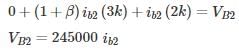
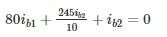
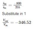
The two stages of the amplifier are shown in the figure. Both transistors have current gain β of 80 and dynamic emitter resistance r′e of 25Ω. The magnitude of the overall voltage gain of the amplifier is approximately
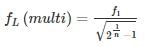
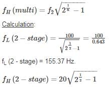
Two RC coupled amplifiers are connected to form a 2-stage amplifier. If the lower and upper cut off frequencies of each individual amplifiers is 100 Hz and 20 kHz. Then the 3-dB bandwidth of the two-state amplifier is ____ Hz.
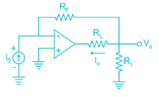
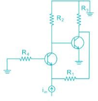
In the AC equivalent circuit shown in Fig, if Iin is the Input current and Feedback Resistance is very large, the type of Feedback
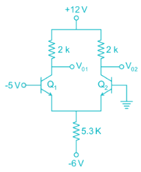
The differential DC output voltage V01 – V02 in the circuit shown is ____ V.

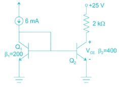
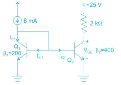
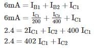
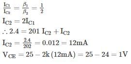
Find the value of VCE in the given figure.
Assume the base currents to be the same.
|
211 videos|208 docs|72 tests
|


Important Questions for Analog Electronics - 4
Analog Electronics - 4 MCQs with Answers
Online Tests for Analog Electronics - 4 Analog and Digital Electronics
|
© EduRev
|
Education Revolution
|


|


