JEE Advanced (Single Correct MCQs): Electromagnetic Induction & Alternating Current - JEE MCQ
16 Questions MCQ Test - JEE Advanced (Single Correct MCQs): Electromagnetic Induction & Alternating Current
A thin circular ring of area A is held perpendicular to a uniform magnetic field of induction B. A small cut is made in the ring and a galvanometer is connected across the ends such that the total resistance of the circuit is R. When the ring is suddenly squeezed to zero area, the charge flowing through the galvanometer is
A thin semi-circular conducting ring of radius R is falling with its plane vertical in horizontal magnetic induction  At the position MNQ the speed of the ring is v, and the potential difference developed across the ring is
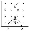
 At the position MNQ the speed of the ring is v, and the potential difference developed across the ring is
Two identical circular loops of metal wire are lying on a table without touching each other. Loop-A carries a current which increases with time. In response, the loop-B
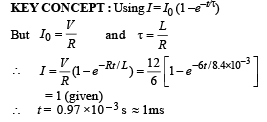
A coil of inductance 8.4 mH and resistance 6 Ω is connected to a 12 V battery. The current in the coil is 1.0 A at approximately the time
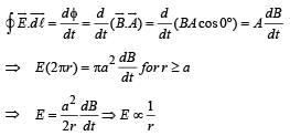
A uniform but time-varying magnetic field B(t) exists in a circular region of radius a and is directed into the plane of the paper, as shown. The magnitude of the induced electric field at point P at a distance r from the centre of the circular region

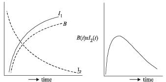
A coil of wire having inductance and resistance has a conducting ring placed coaxially within it. The coil is connected to a battery at time t = 0, so that a time-dependent current l1(t) starts flowing through the coil. If I2(t) is the current induced in the ring, and B(t) is the magnetic field at the axis of the coil due to I1(t), then as a function of time (t > 0), the product I2(t) B(t)
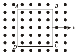
A metallic square loop ABCD is moving in its own plane with velocity v in a uniform magnetic field perpendicular to its plane as shown in the figure. An electric field is induced

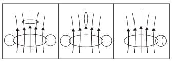
Two circular coils can be arranged in any of the three situations shown in the figure. Their mutual inductance will be

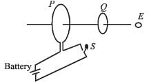
As shown in the figure, P and Q are two coaxial conducting loops separated by some distance. When the switch S is closed, a clockwise current IP flows in P (as seen by E) and an induced current IQ1 flows in Q. The switch remains closed for a long time. When S is opened, a current IQ2 flows in Q.
Then the direction IQ1 and IQ2 (as seen by E) are
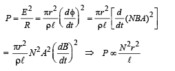
A short-circuited coil is placed in a time-varying magnetic field. Electrical power is dissipated due to the current induced in the coil. If the number of turns were to be quadrupled and the wire radius halved, the electrical power dissipated would be
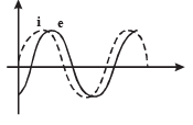
When an AC source of emf e = E0 sin(100t) is connected across a circuit, the phase difference between the emf e and the current i in the circuit is observed to be π/4 , as shown in the diagram. If the circuit consists possibly only of R-C or R-L or L-C in series, find the relationship between the two elements
A small bar magnet is being slowly inserted with constant velocity inside a solenoid as shown in figure. Which graph best represents the relationship between emf induced with time

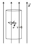
An infinitely long cylinder is kept parallel to an uniform magnetic field B directed along positive z-axis. The direction of induced current as seen from the z-axis will be
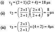
Find the time constant (in μs) for the given RC circuits in the given order respectively
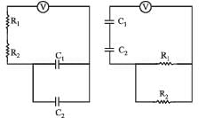
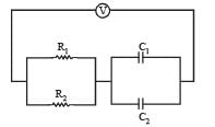
R1 = 1W, R2 = 2W, C1 = 4μF , C2 =2μF
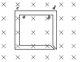
The figure shows certain wire segments joined together to form a coplanar loop. The loop is placed in a perpendicular magnetic field in the direction going into the plane of the figure. The magnitude of the field increases with time. I1 and I2 are the currents in the segments ab and cd. Then,
An AC voltage source of variable angular frequency ω and fixed amplitude V0 is connected in series with a capacitance C and an electric bulb of resistance R (inductance zero). When ω is increased



 decreases with time and hence I2 alsodecreases with time.] Where I1 = Imax (1 – e –t/t)