OP–amp Nat Level – 2 - Physics MCQ
10 Questions MCQ Test - OP–amp Nat Level – 2
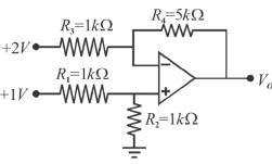
The output Vo of the ideal Op-Amp circuit shown is the figure is (in volts).

The circuit shown below represent a non-inverting integrator. For high frequency input (ω →  ) impedance in ohms is?
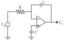
 ) impedance in ohms is?
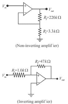
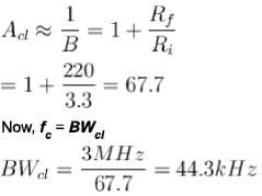
The difference between the bandwidth of the amplifiers given below when both the Not answered Op-Amps have an open loop gain of 100dB and a unity-gain bandwidth of 3MHz (in KHz) is :

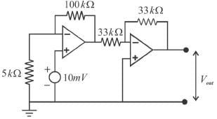
In the given circuit using ideal Op-Amps, the output voltage (in mV) is :
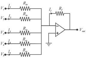
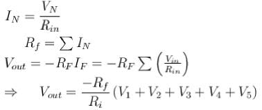
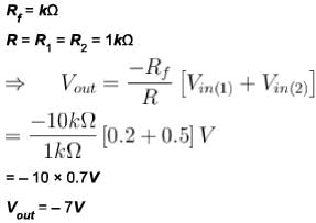
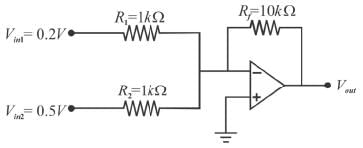
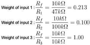
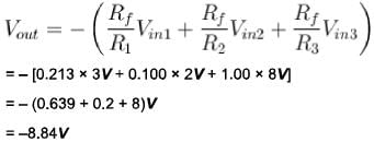
The output voltage for the scaling adder in figure shown below is (in volts)
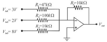
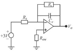
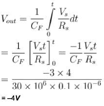
Figure shows a practical integrator with Rs = 30MΩ, RF = 20MΩ and CF = 0.1 μF. If a step (dc) voltage of +3V is applied as input for 0 < t < 4 (t is in seconds), the output voltage is a ramp function. What is the voltage in volts?
The certain inverting amplifier has a closed loop gain of 25. The Op-Amp has an open-loop gain of 100000. If another Op-Amp with an open loop gain of 200000 is substituted in the configuration, the closed loop gain is?
If the voltage gain for each input of a summing amplifier with a 4.7 kΩ feedback resistor is unity, the input resistors must have a value of (in kΩ?
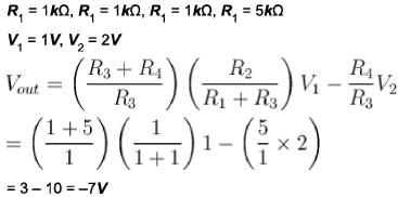
The output voltage for the summing amplifier shown in figure is : (in volts)',



 ) input impedance → 0



 must be?