Test: 1P Diode Rectifiers FW - Electrical Engineering (EE) MCQ
20 Questions MCQ Test - Test: 1P Diode Rectifiers FW

A single-phase full wave mid-point type diode rectifier requires __________ number of diodes whereas bridge type requires _________

In a 1-phase full wave bridge rectifier with M-2 type of connection has secondary side voltage Vs = Vm sin ωt, with R load & ideal diodes.The expression for the average value of the output voltage can be given by
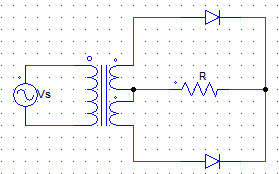
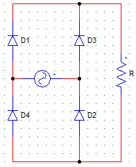
For the circuit shown below, find the power delivered to the R load
Where,
Vs = 230V
Vs is the secondary side single winding rms voltage.
R = 1KΩ
The PIV experienced by the diodes in the mid-point type configuration is
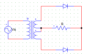
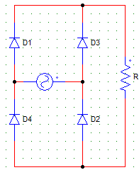
For the circuit shown below, find the value of the average output current.
Where,
Vs = 230V
R = 1KΩ
Vs is the secondary side single winding rms voltage.
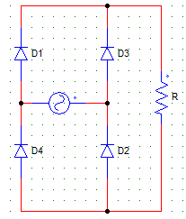
In the circuit, let Im be the peak value of the sinusoidal source current. The average value of the diode current for the below given configuration is
The PIV experienced by each of the diodes for the below shown rectifier configuration is
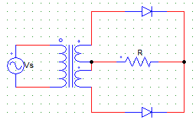
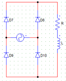
For the circuit shown in the figure below,
Vs = 230 V
R = 10Ω
Find the average value of output current.
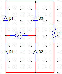
Choose the correct statement regarding the below given circuit.
For a single phase, full bridge, diode rectifier excited from a 230 V, 50 Hz source. With R = 10 Ω & the inductance(L) large enough to maintain continues conduction, the average and rms values of diode currents will be
The circuit shown below, will have the output voltage waveform similar to that of a
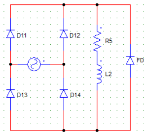
For the circuit shown below, the load current attains the maximum value at ωt =

For a single phase, full bridge, diode rectifier excited from a 230 V, 50 Hz source. With R = 10 Ω & the inductance(L) large enough to maintain continuous conduction, the value of the supply power factor will be
The rectification efficiency for B-2 type & M-2 type full wave diode rectifiers are ___ & ___ respectively.
A load of R = 60 Ω is fed from 1phase, 230 V, 50 Hz supply through a step-up transformer & than a diode. The transformer turns ratio = 2. The power delivered to the load is
For the circuit shown below, D11 & D14 conduct from?
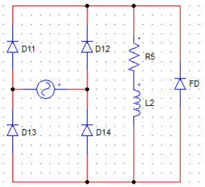
Assume that anode of D12 is positive at ωt = 0 and likewise.
Important Questions for 1P Diode Rectifiers FW
1P Diode Rectifiers FW MCQs with Answers
Online Tests for 1P Diode Rectifiers FW
|
© EduRev
|
Education Revolution
|


|


