Electrical Engineering (EE) Exam  >  Electrical Engineering (EE) Tests  >  Test: Analog Electronics - 6 - Electrical Engineering (EE) MCQ

Test: Analog Electronics - 6 - Electrical Engineering (EE) MCQ


Test Description

25 Questions MCQ Test - Test: Analog Electronics - 6

Test: Analog Electronics - 6 for Electrical Engineering (EE) 2024 is part of Electrical Engineering (EE) preparation. The Test: Analog Electronics - 6 questions and answers have been prepared according to the Electrical Engineering (EE) exam syllabus.The Test: Analog Electronics - 6 MCQs are made for Electrical Engineering (EE) 2024 Exam. Find important definitions, questions, notes, meanings, examples, exercises, MCQs and online tests for Test: Analog Electronics - 6 below.
Solutions of Test: Analog Electronics - 6 questions in English are available as part of our course for Electrical Engineering (EE) & Test: Analog Electronics - 6 solutions in Hindi for Electrical Engineering (EE) course. Download more important topics, notes, lectures and mock test series for Electrical Engineering (EE) Exam by signing up for free. Attempt Test: Analog Electronics - 6 | 25 questions in 25 minutes | Mock test for Electrical Engineering (EE) preparation | Free important questions MCQ to study for Electrical Engineering (EE) Exam | Download free PDF with solutions
Test: Analog Electronics - 6 - Question 1

A voltage tripler circuit and voltage quadrupler circuit use identical components. Then

Detailed Solution for Test: Analog Electronics - 6 - Question 1

Since voltage quadrupler circuit uses more components, voltage drop will be more and voltage regulation poorer.

Test: Analog Electronics - 6 - Question 2

A Ge diode operated at a junction temperature of 27ºC. For a forward current of 10 mA, VD is found to be 0.3 V. If VD = 0.4 V then forward current will be

Detailed Solution for Test: Analog Electronics - 6 - Question 2

iD2 = (47.73) x 10 mA = 466 mA.

1 Crore+ students have signed up on EduRev. Have you? Download the App
Test: Analog Electronics - 6 - Question 3

In a power amplifier the collector current flows for 270º of the input cycle. The operations is

Detailed Solution for Test: Analog Electronics - 6 - Question 3

In class A operation IC exists for 360º. In class B operation IC exists for 180º. In between there is the class AB.

Test: Analog Electronics - 6 - Question 4

An amplifier has input impedance of 4 kΩ and output impedance of 80 kΩ. It is used in negative feedback circuit with 10% feedback. If open loop gain is 90, the closed loop input and output impedances are

Detailed Solution for Test: Analog Electronics - 6 - Question 4

Closed loop input impedance = 4 (1 + 0.1 x 90) = 40 kΩ,

Closed loop Output impedance = = 8 kΩ.

Test: Analog Electronics - 6 - Question 5

In figure the current through resistor R

Detailed Solution for Test: Analog Electronics - 6 - Question 5

.

Test: Analog Electronics - 6 - Question 6

In a negative feedback amplifier A = 100, β = 0.04 and Vs = 50 mV, then feedback will be

Detailed Solution for Test: Analog Electronics - 6 - Question 6

Feed back factor (βA) = 4.

Test: Analog Electronics - 6 - Question 7

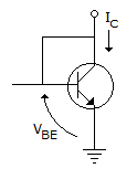
For an npn transistor connected as shown in the figure VBE = 0.7 volts. Given that reverse saturation current of the junction at room temperature 300K is 10-13A, the emitter current.
Detailed Solution for Test: Analog Electronics - 6 - Question 7

IE = aIE + ICBO and approximated.

But a is not given in the question. It is not possible to find.

Test: Analog Electronics - 6 - Question 8

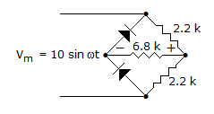
The dc output voltage of the circuit is

Detailed Solution for Test: Analog Electronics - 6 - Question 8

This is half wave Rectifier, because in +ve cycle both the diode will be in forward biased.

For +ve cycle,

Vo max = Imax. Req

2.59 x 10-3 x 1.66 x 103

4.299 volt.

Test: Analog Electronics - 6 - Question 9

A voltage doubler circuit is fed by a voltage Vm sin ωt. The output voltage will be nearly 2 Vm only if

Detailed Solution for Test: Analog Electronics - 6 - Question 9

If load resistance is large, current would be low and voltage drop would be low.

Test: Analog Electronics - 6 - Question 10

The purpose of connecting a coupling capacitor in the output circuit of an amplifier is

Detailed Solution for Test: Analog Electronics - 6 - Question 10

Capacitor acts for ac or dc.

Test: Analog Electronics - 6 - Question 11

Which component is allowed to pass through it by a choke filter?

Detailed Solution for Test: Analog Electronics - 6 - Question 11

XL is zero for dc.

Test: Analog Electronics - 6 - Question 12

In an amplifier the stray capacitances assume impedance at low frequencies

Detailed Solution for Test: Analog Electronics - 6 - Question 12

Stray capacitances assume importance at high frequencies because .

Test: Analog Electronics - 6 - Question 13

In CE amplifier the base current is very high.

Detailed Solution for Test: Analog Electronics - 6 - Question 13

Base current is small.

Test: Analog Electronics - 6 - Question 14

In the graphical analysis of CE amplifier circuit, the upper end of load line is called

Detailed Solution for Test: Analog Electronics - 6 - Question 14

Current is maximum at saturation point.

Test: Analog Electronics - 6 - Question 15

A full wave rectifier supplies a load of 1 kΩ. The a.c. Voltage applied to the diodes is 220 - 0 - 220 Volts rms. If diode resistance is neglected, then Average d.c. Voltage

Detailed Solution for Test: Analog Electronics - 6 - Question 15

.

Test: Analog Electronics - 6 - Question 16

In the graphical analysis of an amplifier circuit, the slope of dc load line depends on

Detailed Solution for Test: Analog Electronics - 6 - Question 16

Slope is .

Test: Analog Electronics - 6 - Question 17

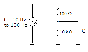
In figure we need an ac ground. The proper value of C is
Detailed Solution for Test: Analog Electronics - 6 - Question 17

XC should be less than 10% of 10 kΩ. There XC < 1000 Ω.

Test: Analog Electronics - 6 - Question 18

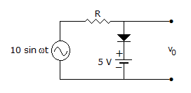
For the circuit in figure the output wave shape is

Detailed Solution for Test: Analog Electronics - 6 - Question 18

It is a biased limiter circuit. During positive half clipping is at 5 V due to battery.

Test: Analog Electronics - 6 - Question 19

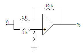
In figure V0 =

Detailed Solution for Test: Analog Electronics - 6 - Question 19

.

Test: Analog Electronics - 6 - Question 20

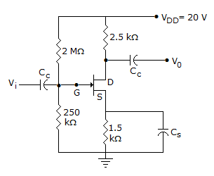
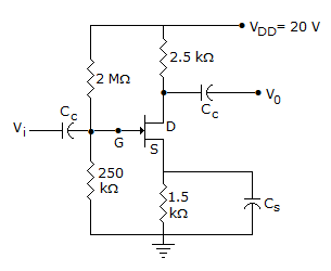
In figure, ID = 4 mA. Then VS =

Detailed Solution for Test: Analog Electronics - 6 - Question 20

VS = 4 x 10-3 x 1.5 x 10-3 = 6 V.

Test: Analog Electronics - 6 - Question 21

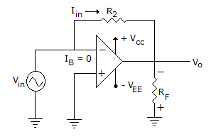
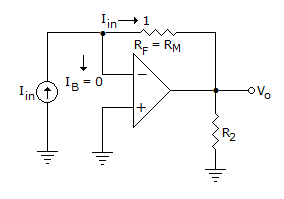
The circuit shown is

Detailed Solution for Test: Analog Electronics - 6 - Question 21

Circuit can be redrawn as.

This is an inverting amplifier with inverting terminal virtual ground.

Hence, Vo = - iin RF

This RF is termed as mutual resistance here, Rm.

output voltage with load

Where R0 is output Resistance of Op-Amp.

if RL >> R0 output terminals become open circuited.

and VoL = Rm.Iin

where Rm work as mutual resistance.

Test: Analog Electronics - 6 - Question 22

Consider 49 cascaded amplifiers having individual rise time as 2 n sec. 3 n sec. ... 50 n sec. The input waveform rise time is 1 n sec. Then the output signal rise time is given time by (Assume output signal rise time is measured within 10 percent range of the final output signal.)

Detailed Solution for Test: Analog Electronics - 6 - Question 22

Output rise time (tr) 1.1ti02 + t12 + ... + t492,

where t, t2 ... t49 are the individual rise time.

tr 1.1 (1 ns)2 + (2 ns)2 + (50 ns)2

1.1 0.228 msec.

Test: Analog Electronics - 6 - Question 23

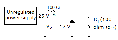
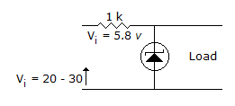
The zener diode in the rectangular circuit shown in the figure has a zener voltage of 5.8 volts and a zener knee current of 0.5 mA. The maximum load current drawn from this circuit ensuring proper functioning over the input voltage range between 20 and 30 volts, is
Detailed Solution for Test: Analog Electronics - 6 - Question 23

It is zener diode, hence 5.8 volt remain constant.

By applying KVL

30 = 1000 Imax + 5.8

Imax = 24.2 mA.

Test: Analog Electronics - 6 - Question 24

In figure, ID = 4 mA. Then VDS =

Detailed Solution for Test: Analog Electronics - 6 - Question 24

VDS = VD - VS = 10-6 = 4 V.

Test: Analog Electronics - 6 - Question 25

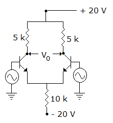
In figure, V0 =

Detailed Solution for Test: Analog Electronics - 6 - Question 25

Both collector terminals are at the same potential.

Information about Test: Analog Electronics - 6 Page
In this test you can find the Exam questions for Test: Analog Electronics - 6 solved & explained in the simplest way possible. Besides giving Questions and answers for Test: Analog Electronics - 6, EduRev gives you an ample number of Online tests for practice

Top Courses for Electrical Engineering (EE)

Download as PDF

Top Courses for Electrical Engineering (EE)