Test: Circuit Analysis in the S-Domain - Electronics and Communication Engineering (ECE) MCQ
20 Questions MCQ Test - Test: Circuit Analysis in the S-Domain
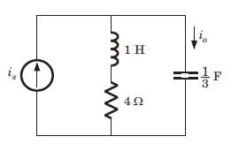
The ratio of the transfer function Io/Is is

The voltage across 200 μF capacitor is given by

The steady state voltage across capacitor is

The transformed voltage across the 60 μF capacitor is given by

The initial current through capacitor is

The current through an 4 H inductor is given by

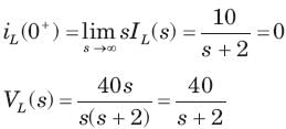
The initial voltage across inductor is
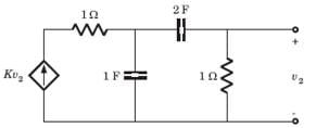
The amplifier network shown in fig.is stable if
A circuit has a transfer function with a pole s = -4 and a zero which may be adjusted in position as s= -a The response of this system to a step input has a term of form Ke -4t. The K will be (H= scale factor)
A circuit has input vin (t) = cos 2t u(t) V and output io (t) = 2sin 2t u(t) A. The circuit had no internal stored energy at t = 0. The admittance transfer function is
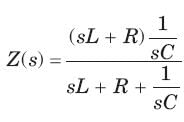
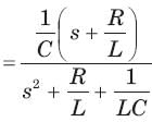
A two terminal network consists of a coil having an inductance L and resistance R shunted by a capacitor C. The poles of the driving point impedance function Z of this network are at  and zero at -1. If Z(0) =1the value of R, L, C are
The current response of a network to a unit step input is

The response is
The circuit is shown in fig.
The current ratio transfer function Io/IS IS
The circuit is shown in fig.
The response is
The circuit is shown in fig.
If input is is 2u(t) A, the output current io is
In the network of Fig. , all initial condition are zero. The damping exhibited by the network is
The voltage response of a network to a unit step input is

The response is
The response of an initially relaxed circuit to a signal vs is e-2t u(t). If the signal is changed to  , the response would be
Consider the following statements in the circuit shown in fig.
1. It is a first order circuit with steady state value of vC= 10/3, i = 5/3A
2. It is a second order circuit with steady state of vC = 2 V , i = 2 A
3. The network function V(s)/I(s)has one pole.
4. The network function V(s)/I(s) has two poles.


 ⇒
⇒ 








 ⇒
⇒ 
 ⇒
⇒ 


 ⇒
⇒ 

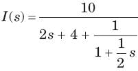

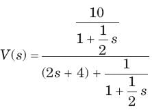

 It has one pole at s = -2

 are real and positive.


