Test: Combinational Logic Circuits - 2 - Electronics and Communication Engineering (ECE) MCQ
10 Questions MCQ Test - Test: Combinational Logic Circuits - 2

Consider the following statements:
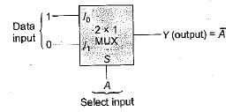
1. When a MUX is used to implement a logic function, the logic variables are applied to the MUX’s data inputs.
2. The circuit for a DEMUX is basically the same as that for a decoder.
Of these:
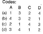
Match List-I (Combinational Circuits) with List-ll (Applications) and select the correct answer using the codes given below the lists:
List-I
A. Decoder
B. Multiplexer
C. Encoder
D. Demultiplexer
List-ll
1. Serial to parallel converter
2. Analog to digital converter
3. Parallel to serial converter
4. Digital to analog converter
A. Decoder
B. Multiplexer
C. Encoder
D. Demultiplexer
1. Serial to parallel converter
2. Analog to digital converter
3. Parallel to serial converter
4. Digital to analog converter

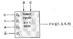
The logic function F(A, B, C) = Σm(1, 3, 5, 6) can be implemented using
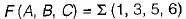 has three variables. Hence, it can be implemented using a multiplexer ( 4 x 1 M U X) with two select inputs and four data inputs.
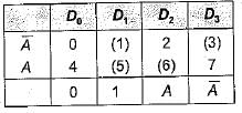
In a binary adder with two inputs X and Y, the correct set of logical expression for the output S (sum) and C (carry) are respectively
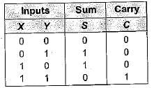
 and carry output is C= XY
A certain multiplexer can switch one of 32 data inputs to its output. The number of control inputs in this multiplexer
Consider the following statements associated with the use of various adder circuits:
1. A ripple carry adder is a parallel adder in which the carry-out of each full-adder is the carry-in to the next most significant adder.
2. Serial adders are used where speed is more important than circuit minimization.
3. The look-ahead carry adder speeds up the process by eliminating the ripple carry.
4. Serial adders are faster than parallel adders
Which of the statements given above are correct?
Assertion (A): The multiplexer can be viewed as a function generator.
Reason (R): The multiplexer acts like a digitally controlled multi-position switch
Assertion (A): Using a decoder could have advantages over using a multiplexer.
Reason (R): The decoder is more economical in cases where non-trivial, multiple-output expressions of the same input variables are required
Assertion (A): The speed of operation of the parallel binary adder is high.
Reason (R): The parallel binary adder is said to generate its output immediately after the inputs are applied.


Important Questions for Combinational Logic Circuits - 2
Combinational Logic Circuits - 2 MCQs with Answers
Online Tests for Combinational Logic Circuits - 2
|
© EduRev
|
Education Revolution
|


|


